Low cost timing device used to accurately advance or retard rotating machine components.
Unique design accommodates both in-line and concentric mounting configurations.
Reduce downtime during machine start-ups and changeovers, while improving product quality.
Product Overview
The Candy Timing Hub is the low cost phase adjusting coupling designed for precise rotary positioning. While in motion, the Timing Hub operates as a rigid shaft coupling. In the static position, it is possible to relocate one of the Timing Hub’s flanges relative to the other, thus changing the rotary position of the output element. When both flanges are secured with the use of drive bolts, the Timing Hub again operates as a rigid shaft coupling.
The ability to advance and retard the position of various machine components is too often accomplished by friction-type clamping mechanisms. Such methods often slip under moderate shock loads, resulting in unnecessary and costly downtime. The Timing Hub eliminates the need for such devices, offering the most economical means of positive position control.
Principle of Operation
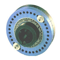
The Timing Hub consists of three major elements: the front flange with 34 holes located about its perimeter, a back flange with 32 holes located about its perimeter, and a pair of drive bolts. The ratio of 34:32 provides for two unobstructed holes for virtually any flange position. These unobstructed holes, located 180 degrees apart, receive the drive bolts, thus securing the flanges together, allowing torque to be transmitted from one to the other.
In operation, the front flange is typically keyed and locked to the drive shaft, while the back flange carries the driven shaft, gear or pulley. When the output element (chain flights, printing cylinder, applicator head etc.) requires adjustment, simply remove the drive bolts, rotate the back flange to the appropriate phase angle and reassemble the Timing Hub. Each consecutive set of holes creates 2/3 of 1 degree phase adjustment.
Technical Data
Construction:
The Timing Hub consists of two flanges and a pair of drive bolts. Each flange is fabricated from a steel hub and a Dupont Zytel mold. Standard hubs are steel with a black oxide finish. The Timing Hub may also be supplied with stainless steel hubs for operation in hostile environments.
The steel hubs are machined to size with pockets which accept the molded Zytel flanges. The Timing Hub flanges with the holes located about the perimeter are then secured together with the use of chrome plated drive bolts.
Positional Accuracy:
Each Timing Hub is supplied with a reference scale on the front hub providing easy location of the unobstructed holes; i.e. hole #10 and the other hole #10 are 180 degrees apart. By changing the location of the drive bolts from the #10 holes to the #9 holes, the rotational position of the output is adjusted by 2/3 of 1 degree.
The largest possible error for each adjustment is 1/2 of an increment, or 1/3 of 1 degree which results in an average positional accuracy of 1/6 of 1 degree.
2 bolts = 544 Locking positions
Incremental adjustment = 2/3 of 1°
Maximum error = 1/2 step = 1/3 of 1º
Average accuracy = 1/6 of 1°
Mounting/Installation
In-Line Shaft
Concentric Shaft
The Timing Hub may be installed in a machine either as an in-line coupling, used to advance or retard the position of the output shaft, or as a concentric shaft coupling providing phase adjustment for parallel shafts.
Note: The Timing Hub is not designed to accommodate misaligned shafts. Misalignment must be isolated from the Timing Hub using either shaft bearing supports or a flexible coupling adapter.
In-Line Shaft Coupling- In order to ensure proper shaft alignment, either the driven or driving shaft should pass completely through one hub and pilot into the other by at least an 1/8".
Concentric Shaft Coupling- The shaft should pass completely through the attached gear or pulley and the Timing Hub at a uniform diameter with a "light" running fit.
Specifications
Standard Bore Specifications
Bore
Keyway
2 Setscrews
one 90º to Keyway
5/16 to 7/16
3/32
#10-32
1/2 to 9/16
1/8
#10-32
5/8 to 7/8
3/16
1/4 - 20
15/16 to 1-1/4
1/4
5/16-18
1-5/16 to 1-3/8
5/16
3/8-16
1-7/16 to 1 3/4
3/8
3/8-16
1-13/16 to 2-1/4
1/2
3/8-16
2-5/16 to 2-1/2
5/8
3/8-16
Face Mounting Specifcations
Model
TH-3
TH-5
TH-8
No. of equally spaced holes
6
3
4
Tap size
#6-32
1/4 - 20
3/8 - 16
Bolt circle
1-1/14"
2-1/4"
3-1/4"
Maximum bore
1"
1-3/4"
2-3/4"
Maximum bore with keyway
3/4"
1-3/8"
2-1/2"
Candy Timing Hub Dimensions and Specifications
Model
TH-3
TH-5
TH-8
Torque lbs./in.
600
1600
6000
Maximum bore
1"
1-3/4"
2-3/4"
Net weight
1-1/4 lb.
5-1/4 lb.
16-1/2 lb.
A
3-1/4"
5"
8"
B
2"
2-3/4"
4"
C
1-1/2"
2-3/4"
4"
D
#8 - 32
1/4 - 20
3/8 - 16
E
29/64"
5/8"
1-1/64"
F
35/64"
3/4"
63/64"
G
.234
.312
.340
H
2-3/4"
4-1/4"
6-7/8"
K
1"
1-3/8"
2"
Ordering/Dimensions
Model
Torque
in lbs.*
Max.
Bore
Net
Weight
A
B
C
D
E
F
G
H
K
TH-3
600
1'
1 1/4 lb.
3 1/4"
2"
1 1/2"
#8-32
29/64"
35/64"
.234
2 3/4"
1"
TH-5
1600
1 3/4"
5 1/4 lb.
5"
2 3/4"
2 3/4"
1/4-20
5/8"
3/4"
.312
4 1/4"
1 3/8"
TH-8
6000
2 1/2"
16 1/2 lb.
8"
4"
4"
3/8-16
1 1/64"
63/64"
.340
6 7/8"
2"
* Reduce ratings for reciprocating applications.
All dimensions and specifications are subject to change without notice.
 The Timing Hub consists of three major elements: the front flange with 34 holes located about its perimeter, a back flange with 32 holes located about its perimeter, and a pair of drive bolts. The ratio of 34:32 provides for two unobstructed holes for virtually any flange position. These unobstructed holes, located 180 degrees apart, receive the drive bolts, thus securing the flanges together, allowing torque to be transmitted from one to the other.
In operation, the front flange is typically keyed and locked to the drive shaft, while the back flange carries the driven shaft, gear or pulley. When the output element (chain flights, printing cylinder, applicator head etc.) requires adjustment, simply remove the drive bolts, rotate the back flange to the appropriate phase angle and reassemble the Timing Hub. Each consecutive set of holes creates 2/3 of 1 degree phase adjustment.
The Timing Hub consists of three major elements: the front flange with 34 holes located about its perimeter, a back flange with 32 holes located about its perimeter, and a pair of drive bolts. The ratio of 34:32 provides for two unobstructed holes for virtually any flange position. These unobstructed holes, located 180 degrees apart, receive the drive bolts, thus securing the flanges together, allowing torque to be transmitted from one to the other.
In operation, the front flange is typically keyed and locked to the drive shaft, while the back flange carries the driven shaft, gear or pulley. When the output element (chain flights, printing cylinder, applicator head etc.) requires adjustment, simply remove the drive bolts, rotate the back flange to the appropriate phase angle and reassemble the Timing Hub. Each consecutive set of holes creates 2/3 of 1 degree phase adjustment.


