Candy Phase Variator
Quick Facts
Adjust the Timing Relationship of Machine Components- 1:1 phase transmissions provide a full 0-360 degree range of position control.
- Economical motion control in a dependable, versatile mechanical design.
- Reduce costly downtime associated with trial and error start-ups and changeovers.
Product Overview
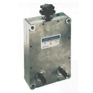
The Phase Variator is the economical timing mechanism used to adjust the position of various machine components-even while running. Installed between the driven machine and the process which requires timing, the Phase Variator provides a full 360 degree range of position control.
In normal operation, with the control knob stationary, the Phase Variator operates as a 1:1 phase transmission with input and output shafts rotating in the same direction. When a rotation is applied to the control knob, a differential action occurs between the input and output shafts allowing a machine operator to synchronize a production process.
This simple, positive timing device is ideal for more efficient machine set-ups and changeovers. The Phase Variator is the low cost answer to the timing challenges facing today’s machine designers.
Principle of Operation
 The Phase Variator's design is simple, yet unique. Each unit is comprised of the following major components: six chain sprockets, a piece of roller chain, a sliding yoke assembly and a control knob.
Sprockets A and B are keyed to the input and output shafts, allowing either to be used as the input. The other four sprockets serve as idlers. Idler sprockets C and D are mounted in a sliding yoke assembly which may be adjusted along its travel by rotating the control knob. An endless roller chain engages all six sprockets as shown in the diagram.
Assume that shaft A, and therefore sprocket A, are stationary. If the control knob is rotated in the counterclockwise direction, the yoke assembly will begin to travel downwards along the threaded control knob shaft. As a result, shaft B will change its position relative to shaft A, as the chain from sprocket C is taken up by sprocket D.
If shaft A is the input and the control knob is rotated in the clockwise direction, shaft B will then advance its position relative to shaft A. If shaft B is the input and the control knob is rotated in the clockwise direction, shaft A will retard its position relative to shaft B. In either direction, the yoke may reach the end of its travel and must then be reversed to make further phase adjustments.
The Phase Variator's design is simple, yet unique. Each unit is comprised of the following major components: six chain sprockets, a piece of roller chain, a sliding yoke assembly and a control knob.
Sprockets A and B are keyed to the input and output shafts, allowing either to be used as the input. The other four sprockets serve as idlers. Idler sprockets C and D are mounted in a sliding yoke assembly which may be adjusted along its travel by rotating the control knob. An endless roller chain engages all six sprockets as shown in the diagram.
Assume that shaft A, and therefore sprocket A, are stationary. If the control knob is rotated in the counterclockwise direction, the yoke assembly will begin to travel downwards along the threaded control knob shaft. As a result, shaft B will change its position relative to shaft A, as the chain from sprocket C is taken up by sprocket D.
If shaft A is the input and the control knob is rotated in the clockwise direction, shaft B will then advance its position relative to shaft A. If shaft B is the input and the control knob is rotated in the clockwise direction, shaft A will retard its position relative to shaft B. In either direction, the yoke may reach the end of its travel and must then be reversed to make further phase adjustments.Technical Data
Construction:
The Phase Variator housing is made from cast aluminum. The input and output shafts are fabricated from steel and have a black oxide finish. The input/output shafts and all internal sprockets are supported by needle bearings with separate oil seals. The combination of the above features provides for a long, trouble-free life.Control knob:
The control knob has an internal thread and engages a centrally located thread shaft which is pinned to the sliding yoke assembly. Rotation of the knob thereby raises and lowers the yoke. The control knob ratio is 36:1. That is, one full turn of the control knob produces a 10° change in the rotational location of the output shaft relative to the input shaft. See principle of operation for position adjustment directions.Chain Adjustment:
If chain wear becomes excessive, the chain may be tensioned without disassembling the unit. The control knob must be rotated until the sliding yoke assembly is at the bottom of its travel. Next, remove the two allen head screws located on the bottom of the housing, exposing the adjusting screws in the base of the yoke assembly. The equal tightening of these screws increases chain tension. After adjustment, the shafts should turn freely with no appreciable backlash.Lubrication:
All Phase Variators are shipped from the factory with a multiple purpose grease lubricant. Although all working parts are well protected, repacking of the bearings may be required in severe operating environments.Mounting/Installation
The standard Phase Variator configuration has both the input and output shafts extending from the front face of the housing. When the Phase Variator is to be driven by sprockets or pulleys, it is sometimes necessary to use drive gears that are larger than the I/O shaft center distance will allow. As a result, it may be necessary to specify the Phase Variator with one of the shafts reversed. Both right-hand and left-hand shaft reverses are available from the factory. All models have (4) mounting holes located in each corner of the housing. Using these mounting holes and the mounting bolts supplied with each unit, the Phase Variator may be either face or back mounted in any position.Ordering
When ordering a Phase Variator, it is important to:- Choose the appropriate size based on required operating torques and speeds. The "E" Stop or maximum torque condition, must be considered when sizing the unit.
- Choose the appropriate shaft configuration: standard, right-hand reverse or left-hand reverse.
Torque Versus RPM
| PV 25 | PV 35-2 | PV 40-2 | |
| Torque @ 50 RPM (lb-in) | 63 | 343 | 793 |
| HP @ 50 RPM | .05 | .27 | .63 |
| Torque @ 500 RPM (lb-in) | 46 | 26 | 627 |
| HP @ 500 RPM | .37 | 2.11 | 5 |
| Torque @ 1200 RPM (lb-in) | 42 | 244 | 576 |
| HP @ 1200 RPM | .81 | 4.64 | 11 |
| Torque @ 1800 RPM (lb-in) | 40 | 234 | 533 |
| HP @ 1800 RPM | 1.16 | 6.68 | 15.23 |
 All units are available with one shaft reversed. Both left-hand and right-hand reverses are available from the factory. Schematic represents a typical left-hand reverse shaft configuration.
Dimensions

| Model | 25 | 35-2 | 40-2 |
| A | 5 | 8 1/4 | 11 |
|---|---|---|---|
| B | 8 | 12 | 16 |
| C | 2 1/4 | 3 1/4 | 5 |
| D | 1 1/4 | 1 3/4 | 2 3/4 |
| E | 3/8 | 3/4 | 1 1/4 |
| F | 2 1/2 | 4 1/4 | 5 1/2 |
| G | 4 1/4 | 7 1/4 | 9 3/4 |
| H | 7 1/4 | 11 | 14 3/4 |
| J | 1 3/4 | 2 1/2 | 3 |
| K | 2 | 3 | 4 |
| L | 11/32 | 7/16 | 9/16 |
| M/kwy | 1/8 | 3/16 | 1/4 |
| N | 1 1/4 | 2 | 2 3/4 |
| O | 1 1/4 | 2 | 2 3/4 |