Candy Harmonic HDD
Quick Facts
Shaft-Mounted Rotary Motion Controls- 1:1 Phase transmission for precise rotary positioning and speed trimming control
- Low backlash and transmission error provides superior positional accuracy in a compact design.
- Reduces costly downtime associated with trial and error machine start-ups and changeovers.
Product Overview
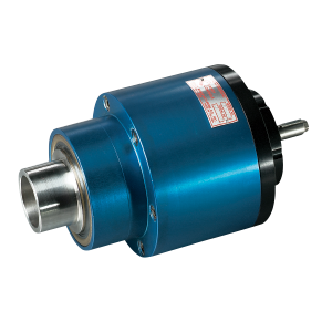
The Candy Harmonic Drive Differential, HDD series, is a shaft-mounted 1:1 transmission which provides infinite, bi-directional position control. When mounted to the end of a roll shaft, the HDD offers static and dynamic phase or speed adjustment. The HDD is a compact, versatile arrangement ideal for retrofit upgrades as well as new machine designs.
When the control shaft is held stationary, the HDD series operates as a 1:1 transmission with input and output members rotating in the same direction. If a rotation is applied to the control shaft, either manually or with a control motor, a differential action occurs between the input and output, making the HDD well suited for position or registration control applications. In addition to positioning, these transmissions may be used for speed trimming or tensioning by applying a constant rotation to the control shaft.
Principle of Operation
The Candy HDD phase shifting differential incorporates two Harmonic Drive pancake gearsets, integrated in a back-to-back arrangement to offset each other's internal ratio. Each gearset is comprised of three major elements: a circular spline, a flexspline and a wave generator. One gearset is attached to the hollow inner shaft, while the second is connected to the outer housing of the HDD.
 Figure 1 represents a simplified view of the torque path through the first of the two pancake gearsets. Assume that the circular spline is the input and the wave generator is stationary. As the circular spline rotates, the flexspline will be carried along with it, but because the flexspline has two less teeth than the circular spline, the flexspline will advance the two tooth difference with each rotation of the circular spline. The gearset, in this arrangement, acts as a slight speed increaser with the flexspline as its output. Next, take an identical pancake gearset and place it in a back-to-back arrangement at the output of the first gearset. The input of the second gearset is its flexspline which is connected to the flexspline output of the first gearset. The output of the second gearset is then the circular spline. Its wave generator is also stationary. The purpose of the second Harmonic Drive gearset is to act as a slight speed decreaser which will cancel the effects of the first gearset, providing a 1:1 transmission.
The control shaft is attached to the bore of one wave generator, but because the HDD has two wave generators, the module has the ability to correct for two independent variables at the same time. Most applications, however, require only one correction input. To visualize the effect of rotating one control shaft, refer to Figure 2. Assume that the flexspline is stationary. With each rotation of the wave generator, the circular spline will advance two teeth in the same direction as the wave generator because the circular spline has two more teeth than the flexspline. In this mode, the Harmonic Drive is functioning as a high ratio reducer. When the concept of Figure 2 is combined with that of Figure 1, the result is a dynamic phase shifting differential with precise position control characteristics.
Figure 1 represents a simplified view of the torque path through the first of the two pancake gearsets. Assume that the circular spline is the input and the wave generator is stationary. As the circular spline rotates, the flexspline will be carried along with it, but because the flexspline has two less teeth than the circular spline, the flexspline will advance the two tooth difference with each rotation of the circular spline. The gearset, in this arrangement, acts as a slight speed increaser with the flexspline as its output. Next, take an identical pancake gearset and place it in a back-to-back arrangement at the output of the first gearset. The input of the second gearset is its flexspline which is connected to the flexspline output of the first gearset. The output of the second gearset is then the circular spline. Its wave generator is also stationary. The purpose of the second Harmonic Drive gearset is to act as a slight speed decreaser which will cancel the effects of the first gearset, providing a 1:1 transmission.
The control shaft is attached to the bore of one wave generator, but because the HDD has two wave generators, the module has the ability to correct for two independent variables at the same time. Most applications, however, require only one correction input. To visualize the effect of rotating one control shaft, refer to Figure 2. Assume that the flexspline is stationary. With each rotation of the wave generator, the circular spline will advance two teeth in the same direction as the wave generator because the circular spline has two more teeth than the flexspline. In this mode, the Harmonic Drive is functioning as a high ratio reducer. When the concept of Figure 2 is combined with that of Figure 1, the result is a dynamic phase shifting differential with precise position control characteristics.Technical Data
Construction:
The HDD differential is designed around reliable Harmonic Drive gear components. The outer housing is anodized aluminum for superior heat dissipation and corrosion resistance. The hollow inner shaft, grounding plate and control shaft are fabricated from stainless steel making the HDD suitable for the harsh environments commonly found in the packaging, printing and converting industries.Versatile Input Configuration:
The HDD has two possible inputs, the hollow inner shaft or the outer housing (which also serves as the gear or pulley pilot). This makes the HDD more versatile than traditional line shaft differentials.
Two control shafts option:
As a result of the back-to-back internal gear design, the HDD has two possible control shafts. The second control shaft, referred to as the "grounding plate", is concentric with the normally used control shaft. One control shaft may be driven at a constant rate for speed trimming (i.e. changing a repeat length without using change gears) while the other control shaft may be used for precise position adjustment. Although the HDD is designed for dual control shaft operation, such applications are rarely encountered in the field. For the majority of applications where only one control shaft is used, it is necessary to ground or secure the second control shaft. See illustrations.
Control Shaft ratio:
The differential action or speed trimming is achieved by rotating the control shaft(s). It is important to note that there are four control shaft ratios to choose from for each HDD size; 81:1, 101:1, 121:1 and 161:1. These ratios define the relationship between the control shaft and the output. For instance, with an 81:1 ratio, an operator would have to rotate the control shaft 81 times to turn the output one full revolution ahead of, or behind, the primary input.Control Shaft Direction of rotation:
Rotating the control shaft in the same direction as the input will cause the output to advance or move ahead of the input. Rotating the control shaft in the opposite direction as the input will cause the output to retard.Control shaft running/holding torque:
Because of the inherent high efficiency of the Harmonic Drive gear components, the HDD control shaft may backdrive. Therefore, it is necessary to apply a holding torque to the control shaft to maintain a 1:1 transmission ratio. Control shaft holding/running torques may be calculated using the following formula: Tcm = T ÷ (Cr x 0.5) Control Motor Torque= Tcm System Torque= T Control Shaft Ratio= Cr The "E" Stop or maximum torque condition must be considered when sizing a control motor or locking knob to avoid backdriving of the control shaft during high torque operation.Speed trimming/tensioning:
Because it is a 1:1 differential, the HDD is most commonly used in positioning applications such as print-to-print or print-to-cut registration control. It is possible to use the HDD as a speed trimming or tensioning device by applying a constant rotation to the control shaft.Example:
Assume that an HDD has an input/output speed of 500 RPM with the control shaft stationary. An operator now finds that the application requires a 1% draw at the output or an additional 5 RPM. For a control shaft ratio of 161:1, the control shaft motor will have to turn 805 RPM. 5 X 161 = 805 RPM If the control shaft is rotated at 805 RPM in the same direction as the input, the output will then rotate 5 RPM faster than the input or 505 RPM. Likewise, if the same 805 RPM rotation is applied to the control shaft in a direction opposite to the input, the output will rotate 5 RPM slower than the input or 495 RPM.Lubrication:
The Candy HDD is filled and shipped from the factory with the recommended lubrication, Lubriplate SPO-277 gear oil. All units are shipped with a plug at the end of the control shaft to prevent leakage during transportation. Before installing the HDD, it is necessary to remove the plug and install the provided vent at the end of the control shaft. Operating temperature of the oil should not exceed 200° F. For harsh environments, or severe applications, please consult the factory for more information.Dynamic Balancing:
HDD applications that require housing speeds in excess of 2,800 RPM may require dynamic balancing. Please consult the factory for more information.Performance Information
| Size & Ratio | Torque 500 RPM | Torque 1750 RPM | Torque 3500 RPM | Maximum Output Torque* | Maximum Relative RPM** | Weight lbs. (Approx.) |
| HDD 20 | ||||||
|---|---|---|---|---|---|---|
| 81:1 | 250 | 246 | 195 | 250 | 6000 | 7 |
| 101:1 | 300 | 246 | 195 | 300 | 6000 | 7 |
| 121:1 | 350 | 246 | 195 | 350 | 6000 | 7 |
| 161:1 | 375 | 246 | 195 | 390 | 6000 | 7 |
| HDD 25 | ||||||
| 81:1 | 425 | 406 | 320 | 425 | 5000 | 14 |
| 101:1 | 600 | 406 | 320 | 600 | 5000 | 14 |
| 121:1 | 615 | 406 | 320 | 700 | 5000 | 14 |
| 161:1 | 615 | 406 | 320 | 780 | 5000 | 14 |
| HDD 32 | ||||||
| 81:1 | 950 | 810 | 640 | 950 | 4500 | 25 |
| 101:1 | 1200 | 810 | 640 | 1200 | 4500 | 25 |
| 121:1 | 1230 | 810 | 640 | 1400 | 4500 | 25 |
| 161:1 | 1230 | 810 | 640 | 1550 | 4500 | 25 |
| HDD 50 | ||||||
| 81:1 | 3100 | 3180 | 2525 | 3100 | 3500 | 65 |
| 101:1 | 4200 | 3180 | 2525 | 4200 | 3500 | 65 |
| 121:1 | 4825 | 3180 | 2525 | 5200 | 3500 | 65 |
| 161:1 | 4825 | 3180 | 2525 | 5800 | 3500 | 65 |
| HDDX 50 | ||||||
| 81:1 | 5110 | 3890 | 3085 | 5110 | 3500 | 70 |
| 101:1 | 6500 | 4860 | 3855 | 6500 | 3500 | 70 |
| 121:1 | 7380 | 4860 | 3855 | 9500 | 3500 | 70 |
| 161:1 | 7380 | 4860 | 3855 | 13100 | 3500 | 70 |
Mounting/Installation
Mounting :
The HDD has a hollow inner shaft which is machined specifically for each application in order to mount over the end of the machine shaft. To maintain concentricity and for superior axial retention, Candy recommends one of two mounting methods. A. External shrink-disk bushing. For this configuration, Candy must extend the length of the hollow inner shaft to accommodate the bushing. The shrink-disk bushing is placed over the outer diameter of the hollow shaft and the HDD is then placed over the end of the machine shaft. By tightening the locking screws, the bushing clamps down on the hollow shaft and the machine shaft, thus securing the connection. B. Internal compression type bushing. The bushing is inserted into the bore of the hollow inner shaft and then the HDD and bushing are placed over the end of the machine shaft. By tightening the locking screws, the bushing expands into the hollow shaft while at the same time clamps down on the machine shaft.
 Candy also recommends the use of a suitable support bracket secured to the machine frame. This bracket serves several purposes, the most important of which is to secure the HDD axially to the machine. The bracket may also be used to secure the grounding plate and a control motor or locking knob assembly.
When installing the support bracket it is imperative that the HDD assembly is aligned correctly. Misalignment caused by improper installation may damage the differential.
If the described mounting methods are not suitable for your application, please consult the factory for alternative mounting suggestions.
Candy also recommends the use of a suitable support bracket secured to the machine frame. This bracket serves several purposes, the most important of which is to secure the HDD axially to the machine. The bracket may also be used to secure the grounding plate and a control motor or locking knob assembly.
When installing the support bracket it is imperative that the HDD assembly is aligned correctly. Misalignment caused by improper installation may damage the differential.
If the described mounting methods are not suitable for your application, please consult the factory for alternative mounting suggestions.
Installation :
The Candy HDD is simple to install making this series ideal for machine retrofits as well as new machine designs. The following illustrations may serve as a guide for designing phase or speed control into your machine.
 Remove the existing gear or pulley from the machine shaft journal or for a new design, purchase the appropriate gear or pulley.
- Open the bore of the gear or pulley to fit over the pilot diameter (dimension D) on the outer housing of the HDD. After the bore is opened, add mounting holes to the gear or pulley in order to secure it to the HDD's outer housing.
- Mount the remachined gear or pulley to HDD's outer housing using the tapped holes that are provided on each HDD unit (dimension W-BCD).
- The differential and gear are now ready to be mounted on the end of the machine shaft. Please refer to the previous section for preferred mounting methods.
- Running torque and inertia calculations
- Providing alternative mounting suggestions
- Machining and mounting gears or pulleys
- Supplying shaft bushings
 Typical Mounting for Manual Control
Ordering/Dimensions
When ordering an HDD, it is important to:- Properly size the HDD unit based on required torque and operating speeds. The "E" Stop or maximum torque condition must be considered when sizing the unit.
- Choose the appropriate control shaft ratio for the application.
- Select the mounting method that best suits the application. Decision must include machine shaft diameter and desired bushing style.


| Size | A* | B* | C | D | E | F* | G | H | J | K | L | M | N | P* |
| HDD 20 | 7.06 | 1.417 | 4.00 | 2.875 | 1.875 | 1.10 | 1.00 | 3.24 | .38 | 0.12 | .60 | 2.16 | 0.937 | 2.10 |
| HDD 25 | 8.11 | 1.890 | 4.50 | 3.313 | 2.250 | 1.30 | 1.50 | 3.37 | .50 | 0.12 | .69 | 2.76 | 1.375 | 2.40 |
| HDD 32 | 8.77 | 2.362 | 5.63 | 3.875 | 2.750 | 1.30 | 1.63 | 3.83 | .50 | 0.13 | .63 | 3.74 | 1.875 | 2.80 |
| HDD 50 | 12.55 | 3.150 | 8.00 | 6.000 | 4.250 | 1.83 | 2.31 | 6.09 | .50 | 0.13 | .44 | 4.50 | 2.500 | 4.00 |
| HDDX 50 | 12.56 | 2.756 | 8.00 | 5.250 | 3.500 | 1.77 | 2.25 | 7.44 | .50 | 0.22 | .38 | 4.50 | 2.500 | 4.12 |
| Size | R | S | T (Square) | W-BCD | Y-BCD | Max Radial Load |
| HDD 20 | 1.00 | 3.75 | 0.094 X .50Lg | (6) 1/4-20 on 3.438 BCD | (3) 6-32 on 0.750 BCD | 640 lbs |
| HDD 25 | 1.13 | .437 | 0.094 X .63Lg | (6) 1/4-20 on 3.906 BCD | (3) 8-32 on 1.125 BCD | 970 lbs. |
| HDD 32 | 1.25 | .500 | 0.125X .88Lg | (6) 5/16-18 on 4.750 BCD | (3) 1/4-20 on 1.500 BCD | 1330 lbs. |
| HDD 50 | 1.75 | .750 | 0.188 X 1.13Lg | (6) 3/8-16 on 7.000 BCD | (3) 5/16-18 on 1.875 BCD | 3710 lbs. |
| HDDX 50 | 1.50 | .750 | 0.188 X 1.13Lg | (6) 3/8-16 on 6.750 BCD | (3) 5/16-18 on 2 BCD | 3710 lbs. |