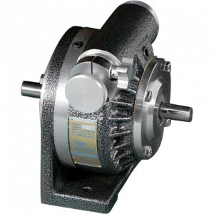
The Adjustable-While-Running Precision Timing Mechanism
Shaft Positioning
Registration Control
Speed Trimming
Product Overview
Power transfer through the Dynamic Differential begins at the input shaft, transfers at right angles through the spider gears, and then back to the output shaft to provide a 1:1 ratio, reverse rotation drive. To change timing or angular position between the input and output shafts, the spider gears are rotatable about the main shaft centerline. Adjusting the worm rotates the worm gear which shanges the position of the spider gears in relation to the pinion gears. Suppose that the input shaft is stationary. If the spider gears are repositioned by means of the adjusting worm, the movement of the spiders causes a related change in position of the output shaft. Since this control action in independent of the drive function, this adjustment can be made while the drive is in motion to provide precise, while running, timing control.
Principle of Operation
Power transfer through the Dynamic Differential begins at the input shaft, transfers at right angles through the spider gears, and then back to the output shaft to provide a 1:1 ratio, reverse rotation drive. To change timing or angular position between the input and output shafts, the spider gears are rotatable about the main shaft centerline. Adjusting the worm rotates the worm gear, which changes the position of the spider gears in relation to the pinion gears. Suppose that the input shaft is stationary. If the spider gears are repositioned by means of the adjusting worm, the movement of the spiders causes a related change in position of the output shaft. Since this control action is independent of the drive function, this shaft adjustment can be made while the drive is in motion to provide precise, while running, timing control.
Applications
The Dynamic Differential is a precision timing mechanism used to advance or retard timing of mechanical actions. Installed in the drive train to the component to be controlled, these timing differentials may be manually or motor adjusted while running or stopped. The input and output shafts rotate in a 1:1 ratio, counter-rotating relationship. Either shaft may be used as the input. When the control knob is adjusted the; output shaft advances or retards its angular position relative to the input shaft. Correction is unlimited in either direction.
Shaft Positioning
Because the Dynamic Differential is both a positive drive and adjustable while it is an excellent solution to problems involving timing relationships of machine components. If, for example, a cut-off knife or a feeder mechanism is operating a little too late, you simply turn the control knob, even while running, to establish the exact timing required for optimum performance.
Registration
When there is variable or cumulative timing error in a machine process a motor controlled differential is used to automatically compensate for those errors. If a packaging machine is wrapping candy bars using a web of pre-printed plastic film there will be a cumulative error in the process because of stretch or shrink of the film causing misalignment between the candy bar and the wrapper. The solution lies in a registration system using an electric eye and a controller to operate the differential. Please consult factory for full details on complete systems.
Speed Trimming
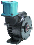
The Dynamic Differential can also be used to modify speed. By the use of a customer supplied motor to drive the control shaft the Dynamic Differential may be used to add or subtract a few RPM to a given input RPM. This speed trimming can be at a fixed speed, variable speed or intermittent. Please consult factory for details.
Options: Control Shaft, Control motor and same shaft rotation units.
Technical Data
Technical Data
DD-1A
DD-5A
DD-5ALS
DD-15A
HP Rating
1 @ 1,800 rpm
5 @ 1,200 rpm
5 @ 1,200 rpm
15 @ 1,800 rpm
Torque (inch lbs) @ 1750 RPM
36
225
225
600
Torque (inch lbs) @ 375 RPM
45
300
300
800
Torque (inch lbs) @ 100 RPM
50
350
350
1,000
Maximum Static Torque (inch lbs)
65
500
500
1500
Maximum Overhung Load (lbs.)
75
225
225
575
Degrees of Rotation
(1-turn of Control Knob)
14.4
12
12
9
360 Degree Rotation
(Control Knob Rotation)
25
30
30
40
Net Weight (lbs)
11
24
32
82
DD-5ALS is a Line Shaft unit with input and outputs shafts rotating in the same direction.
Control Shaft in Place of The Knob
Model
DD-1A
DD-5A
DD-5ALS
DD-15A
A
3.03
4.75
4.75
5.95
B
4.38
7.25
7.25
10.00
C
.938
1.44
1.44
1.50
D
.312
.374
.374
.498
E
3/32 x 3/32 x 3/4
1/8 x 1/8 x 3/4
1/8 x 1/8 x 3/4
1/8 x 1/8 x 1-1/4
(Optional Key)
All units in inches
Ordering/Dimensions
Model
DD-1A
DD-5A
DD-5ALS
DD-15A
Model
DD-1A
DD-5A
DD-5ALS
DD-15A
A
1/2
3/4
3/4
1-1/4
O
4-1/2
5-3/8
5-9/16
10-1/4
B
4-7/16
7
7
10-1/8
P
3/8
3/4
21/32
13/16
C
6
8-3/4
11-7/8
16-3/4
Q
2-1/4
2-11/16
2-25/32
5-1/8
D
2-19/32
3-3/4
3-3/4
7
R
3-3/8
4-15/16
4-15/16
6-1/4
E
1
1-1/2
1-1/2
2-5/8
S
1-1/2
2
2
2-3/4
F
0
0
3-1/8
4-1/2
T
2-1/2
4-1/4
4-1/4
5-3/8
G
1-1/8
2
5/8
3/4
U
11/32
7/16
7/16
9/16
H
1-1/8
2
2-3/16
3
V
2
2
4
4
I
1-7/8
3-1/8
3-5/8
5-3/8
W
10-24
5/16-18
J
2-1/4
3-3/8
4-3/8
6
X
2-3/4
6-1/8
K
1/8 sq.
3/16 sq.
3/16 sq.
1/4 sq.
Y
1/2
13/16
5/8
7/8
L
5-1/8
8-7/16
8-7/16
11-3/8
Z
1-7/8
5-1/8
M
4-3/8
7-1/4
7-1/4
10
O.D.
4-1/2
7-1/8
7-1/8
10-1/8
N
5-1/4
6-7/8
6-7/8
11-7/8
All units are inches.
Model
Rate of Correction for Output Shaft (Degrees per minute)


 Slo-Syn®motor control. Stepping/Synchronous motor. 120 VAC, 60HZ, reversible, continous duty, contant speed.