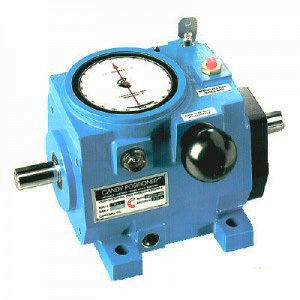
Candy Positioner
Quick Facts
Rotary Motion Control - Even While Running- 1:1 Phase transmission with 400 degrees of precise rotary adjustability.
- Eliminates costly downtime associated with trial and error start-ups and changeovers.
- Unique design provides the highest degree of quality, durability and economy.
Product Overview
The Candy Positioner, POSI series, is a phase shifting mechanism used to accurately adjust and “fine tune” the timing relationship of machine actions.
In normal operation, the Positioner is a 1:1 phase transmission with input and output shafts rotating in the same direction. When the control shaft is rotated, a differential action occurs between the input and output shafts. This adjustment may occur while the machine is in the static position or while running.
By providing “on the fly control”, the Positioner eliminates costly downtime associated with production set-ups and changeovers.
The Positioner has been developed to enhance the machine designer’s competitive advantage by maximizing production efficiency.
Principle of Operation
The Candy Positioner offers the ideal balance of :precise control • economy • quality • durability
Because there are no meshing gears typical of traditional gearboxes, the Candy Positioner is an exceptionally quiet, cool running and long lasting rotary motion control device. The Positioner employs a spline drive assembly to achieve phase adjustments, allowing either in-line shaft to be used as the input. The input and output shafts have helical splines cut integrally at the inboard ends, one left-hand spline and one right-hand spline. A rotating sleeve with an internal or female spline at either end, one left-hand and one right-hand, locks the input and output shafts together rotating with them at a 1:1 ratio. When the control knob is rotated, a mechanism shifts or slides the splined sleeve from one end of the travel to the other. The splined sleeve shifting across the male splines creates a twisting action, changing the angular position between the input and output shafts. The Positioner provides a 400 degree differential range, with 200 degrees of angular adjustment in either the advance or retard direction (from the center position with both the keyseats in-line).Technical Data

Construction:
The Candy Positioner is constructed from quality materials and has been designed to operate in harsh environments commonly found in the packaging, printing and converting industries. The housing is aluminum and is coated with a USDA approved epoxy finish. The stainless steel input and output shafts incorporate a patented internal backbone design and are supported by Timken bearings. This combination provides superior overhung load capacity.Control shaft:
Rotating the control shaft of the Positioner creates a differential action between the input and output shafts. By rotating the control shaft in the same direction as the input, the output will advance ahead of the input. Likewise, by rotating the control shaft in a direction opposite to the input, the output will retard.Standard units are shipped with a knob mounted on the control shaft for manual phase adjustments. The Positioner is also available with a keyed shaft in place of the knob. Note: If you plan to design a control motor assembly, remember that the Positioner is not infinitely adjustable.Dial Indicator:
The Positioner has a built-in dial which indicates relative shaft location within the 400 degree range. Starting at zero, the center of the adjustment range, the dial scale reads 0 to 200 degrees in both the advance and retard directions. The lexan protected dial only moves when a rotation is applied to the control shaft. By noting the numerical relative position, an operator can quickly and accurately return to a previously established or desired position.Key Lock:
The Positioner also has a built-in key lock which not only prevents unauthorized adjustments, but also ensures that the Positioner will not drift out of adjustment under severe vibration.Lubrication:
All Phase Variators are shipped from the factory with a multiple purpose grease lubricant. Although all working parts are well protected, repacking of the bearings may be required in severe operating environments.Mounting/Installation


 The Positioner housing has feet for traditional gearbox mounting.
Wall mounts and ceiling mounts are also available.
These alternative mounting arrangements must be specified upon ordering.
When the Positioner is installed in a ceiling mount arrangement, the dial indicator housing will fill with oil. In either the ceiling or wall mount arrangement, it is necessary to relocate vent and drain plug locations.
The Positioner housing has feet for traditional gearbox mounting.
Wall mounts and ceiling mounts are also available.
These alternative mounting arrangements must be specified upon ordering.
When the Positioner is installed in a ceiling mount arrangement, the dial indicator housing will fill with oil. In either the ceiling or wall mount arrangement, it is necessary to relocate vent and drain plug locations.Performance
| POS-1/2 | POSI-2 | POSI-7 | |
| Shaft diameter, inches | .500 | .750 | 1.125 |
|---|---|---|---|
| HP rating @ 1750 RPM | .5 | 2.0 | 7.0 |
| Torque, inch lbs. @ 1750 RPM | 18.0 | 72.0 | 252.1 |
| Torque, inch lbs. @ 375 RPM | 26.6 | 114.3 | 400.2 |
| Torque, inch lbs. @ 100 RPM | 42.5 | 170.0 | 595.0 |
| Maximum static torque, inch lbs. | 66 | 270 | 900 |
| Maximum overhung load, lbs.* | 125 | 250 | 500 |
| Control knob correction rate | 6° /turn | 6° /turn | 4° /turn |
| Maximum phase shift | 400° | 400° | 400° |
| Total control knob turns | 66 2/3 | 66 2/3 | 100 |
| Control knob torque, inch lbs.** | 3.7 | 15.4 | 38.4 |
| WK2, pound inch squared | .14 | 1.28 | 6.46 |
| Full load efficiency, percent | 94.0 | 95.5 | 96.0 |
| Weight, pounds | 6 | 18 | 41 |
Ordering/Dimensions


| Model | POSI- 1/2 | POSI- 2 | POSI- 7 | |
| A | 1/2 | 3/4 | 1 1/8 | +.000 -.001 |
|---|---|---|---|---|
| B | 1 7/8 | 3 | 3 1/2 | +.000 -.003 |
| C | 2 7/8 | 4 1/2 | 5 1/2 | |
| D | 3 1/2 | 5 1/2 | 7 | |
| E | 3 1/2 | 4 1/4 | 6 1/2 | |
| F | 5/16-18 | 3/8-16 | 7/16-14 | |
| G | 1 | 1 1/8 | 1 3/8 | |
| H | 7 3/8 | 10 1/4 | 14 1/2 | |
| I | 5 1/4 | 7 1/2 | 8 3/4 | |
| J | 2 15/16 | 4 9/16 | 5 1/4 | |
| K | 1 | 1 1/2 | 2 1/4 | |
| L | 4 1/16 | 6 1/16 | 7 15/16 | |
| M | 1 5/8 | 2 5/8 | 3 5/8 | + or - .005 |
| N | 1/8 sq. | 3/16 sq. | 1/4 sq. | |
| O | 11/32 | 17/32 | 11/16 | |
| P | 7/16 | 3/4 | 7/8 | |
| Q | 4 1/4 | 6 3/4 | 8 1/2 | |
| R | 1 15/16 | 3 | 4 | |
| S | 1/4 | 5/16 | 3/8 | |
| T | 3 | 4 5/8 | 6 1/4 | |
| U | 3 3/16 | 4 1/4 | 6 |