Candy Harmonic HDC
Quick Facts
Shaft-Mounted Rotary Motion Controls- Precise draw transmissions with a 1/2 to 2% built-in gain between input and output elements.
- Zero backlash and low transmission error in a unique, compact hollow shaft design.
- Reduces costly downtime associated with trial and error machine start-ups and changeovers.
Product Overview
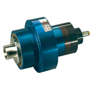
The Candy Harmonic Drive Cup-Type Differential, HDC series, is a shaft-mounted transmission typically used for speed trimming, tensioning, and position control. Unlike the HDD series, the HDC is not a 1:1 differential. With the control shaft held stationary, the HDC has a built-in gain or draw. The amount of gain, between the input and output members is determined by the control shaft ratio.
When mounted to the end of a machine shaft, the HDC offers a unique, compact configuration suitable for both retrofits and new machine designs. The HDC may enhance your competitive advantage by reducing costly downtime and material waste associated with machine start-ups and changeovers.
Principle of Operation

 The Candy HDC incorporates a cup type Harmonic Drive gearset comprised of three major components: a circular spline, a flexspline and a wave generator. The outer housing of the HDC is connected to the circular spline, the hollow inner shaft is connected to the flexspline and the control shaft is keyed to the bore of the wave generator.
Figure 1 represents a simplified view of the torque path thru the HDC. Assume that the circular spline is the input, the hollow inner shaft is the output (these functions can be reversed to achieve a built-in negative gain), and the wave generator is stationary. As the outer housing (circular spline) rotates, it carries with it the hollow inner shaft (flexspline). Because the flexspline has two less teeth than the circular spline, the flexspline will advance the two tooth difference with each rotation of the circular spline. The result of this drive arrangement is a constant built-in (positive) draw.
The built-in constant draw can be dynamically increased or decreased by rotating the control shaft which has been stationary until now. To visualize the effect of rotating the control shaft, assume the outer housing (circular spline) is stationary for the moment as shown in Figure 2. With each rotation of the wave generator, the flexspline will rotate two teeth in a direction opposite to that of the wave generator because the flexspline has two less teeth than the circular spline. In this mode, the Harmonic Drive is functioning as a high ratio reducer.When the concept of Figure 2 is combined with that of Figure 1, the result is a dynamic differential with exceptionally precise speed control characteristics.
The Candy HDC incorporates a cup type Harmonic Drive gearset comprised of three major components: a circular spline, a flexspline and a wave generator. The outer housing of the HDC is connected to the circular spline, the hollow inner shaft is connected to the flexspline and the control shaft is keyed to the bore of the wave generator.
Figure 1 represents a simplified view of the torque path thru the HDC. Assume that the circular spline is the input, the hollow inner shaft is the output (these functions can be reversed to achieve a built-in negative gain), and the wave generator is stationary. As the outer housing (circular spline) rotates, it carries with it the hollow inner shaft (flexspline). Because the flexspline has two less teeth than the circular spline, the flexspline will advance the two tooth difference with each rotation of the circular spline. The result of this drive arrangement is a constant built-in (positive) draw.
The built-in constant draw can be dynamically increased or decreased by rotating the control shaft which has been stationary until now. To visualize the effect of rotating the control shaft, assume the outer housing (circular spline) is stationary for the moment as shown in Figure 2. With each rotation of the wave generator, the flexspline will rotate two teeth in a direction opposite to that of the wave generator because the flexspline has two less teeth than the circular spline. In this mode, the Harmonic Drive is functioning as a high ratio reducer.When the concept of Figure 2 is combined with that of Figure 1, the result is a dynamic differential with exceptionally precise speed control characteristics.Technical Data
Construction
The HDC uses zero-backlash, cup-type Harmonic Drive gear components. The outer housing is made from light weight anodized aluminum for superior heat dissipation and corrosion resistance. The hollow inner shaft and the control shaft are fabricated from stainless steel making the HDC suitable for the harsh environments typically found in packaging, printing and converting industries. Versatile Input Configuration: The HDC has two possible input members, the hollow inner shaft or the outer housing (which also serves as the gear or pulley pilot). This makes the HDC exceptionally versatile in its application. It is important to note which member is being used as the input when calculating output speeds and control shaft running/holding torques. See calculation examples below for more details.
Control Shaft ratio
The HDC is available with several different control shaft ratios including; 50:1, 60:1, 80:1, 100:1, 160:1 or 200:1. These ratios define the relationship between the control shaft and the output. The control shaft ratio also determines the amount of built-in gain or draw. For instance, the selection of the 100:1 control shaft ratio will provide a 1% gain or draw between the input and output housings.Control Shaft speed and direction of rotation
Rotation of the control shaft at a constant speed will add to or subtract from the built-in gain of the HDC. Again, it is important to note which member is being used as the input and in which direction the control shaft is being rotated. See calculation examples below for more details.Control Shaft Running/Holding Torque
Because of the inherently high efficiency of the Harmonic Drive gear components, the HDC control shaft may backdrive. It is therefore necessary to apply a holding torque to the control shaft to prevent drifting. The calculation of this running/holding torque is again dependent on which HDC member is being used as the input.Phase Adjusting
Because the HDC module has a built in gain or draw, it is typically used as a tensioning or draw transmission. The HDC may also be used as a 1:1 phase adjusting differential, taking advantage of its zero backlash characteristics. This may be accomplished in one of three ways. By applying a constant rotation to the control shaft, to match the outer housing speed, it is possible to accurately offset the HDC's internal ratio, making it a 1:1 drive. Another way is to introduce into the drive train the reciprocal of the HDC's internal ratio (see sketch).
 A third option is to attach the housing of a brake motor (actuated through slip rings) to the outer housing of the differential. The motor shaft is coupled to the control shaft. All internal parts of the HDC would thus rotate at the same speed with the motor unenergized, providing a 1:1 drive. When the motor is activated, the output will advance or retard with respect to the input depending on motor direction.
Lubrication
The HDC is filled and shipped from the factory with the recommended lubrication, Lubriplate SPO-277 gear oil. All units are shipped with a plug in place of a vent at the end of the control shaft. Prior to installation it is necessary to remove the plug and insert the provided vent. The operating temperature of the oil should not exceed 200°F. For harsh environments or severe applications, please consult the factory for more information.Input through outer housing
 Most HDC applications such as infeeds, draw stations and chill roll stands use the outer housing as the input, with the hollow inner shaft serving as the output.
A) In this arrangement with the control shaft held stationary, the output (inner shaft) will rotate slightly faster than the input by the fraction shown in column A, Table 1(below).
Example: Assume that the input rotates at 800 RPM and that the control shaft ratio is 160:1. With the control shaft held stationary, the output will rotate at:
800 RPM X (161 ÷ 160) = 805 RPM
B) Rotating the control shaft in the opposite direction to the input will advance or increase the speed of the output. Likewise, rotating the control shaft in the same direction as the input will retard or slow the output. In either case, the effect of the control shaft speed on the output will be: Change in output speed = Control Shaft RPM ÷ Control Shaft Ratio
Example: Assume that the output (hollow inner shaft) rotates at 805 RPM with a stationary 160:1 control shaft. If the control shaft is then rotated at 960 RPM, its effect on the output speed will be:
Most HDC applications such as infeeds, draw stations and chill roll stands use the outer housing as the input, with the hollow inner shaft serving as the output.
A) In this arrangement with the control shaft held stationary, the output (inner shaft) will rotate slightly faster than the input by the fraction shown in column A, Table 1(below).
Example: Assume that the input rotates at 800 RPM and that the control shaft ratio is 160:1. With the control shaft held stationary, the output will rotate at:
800 RPM X (161 ÷ 160) = 805 RPM
B) Rotating the control shaft in the opposite direction to the input will advance or increase the speed of the output. Likewise, rotating the control shaft in the same direction as the input will retard or slow the output. In either case, the effect of the control shaft speed on the output will be: Change in output speed = Control Shaft RPM ÷ Control Shaft Ratio
Example: Assume that the output (hollow inner shaft) rotates at 805 RPM with a stationary 160:1 control shaft. If the control shaft is then rotated at 960 RPM, its effect on the output speed will be:
960 ÷160 = ± 6 RPM
If the control shaft is rotated in a direction opposite to that of the input (outer housing) the output speed =805 RPM + 6 RPM = 811 RPM
If the control shaft is rotated in the same direction as the input the output speed =805 RPM - 6 RPM = 799 RPM
C) Running and holding torques for the control shaft can be calculated with the following formula: Tcs = (T) ÷ (Cr x E) Control Motor Torque= Tcs System Output Torque= T Control Shaft Ratio= Cr Efficiency (Found in Table 1)= EInput through hollow shaft
 If an application requires that the hollow inner shaft be used as the input, the outer housing will then serve as the output and will rotate slightly slower than the input, with the control shaft stationary.
A)To calculate the output speed, with the control shaft stationary, you must use the inverse of the fraction in column A, Table 1(below).
Example: Assume that the input rotates at 800 RPM with a stationary 160:1 control shaft. The output would then rotate at:
800 RPM X (160 ÷ 161) = 795 RPM
B) The effective ratio of the control shaft when used for speed trimming will be one greater than the stated ratio in Table 1(below).
Example: For a stated ratio of 160:1, the effective ratio will become 161:1 for speed trimming calculations.
C) Rotating the control shaft in the same direction as the input will advance or add speed to the output (outer housing). If the control shaft is rotated in a direction opposite to that of the input, the output will then retard or subtract speed from the output.
Example: Assume that the output housing rotates at 795 RPM with a stationary 160:1 (stated ratio) control shaft. If the control shaft is then rotated at 960 RPM its effect on the output will be:
If an application requires that the hollow inner shaft be used as the input, the outer housing will then serve as the output and will rotate slightly slower than the input, with the control shaft stationary.
A)To calculate the output speed, with the control shaft stationary, you must use the inverse of the fraction in column A, Table 1(below).
Example: Assume that the input rotates at 800 RPM with a stationary 160:1 control shaft. The output would then rotate at:
800 RPM X (160 ÷ 161) = 795 RPM
B) The effective ratio of the control shaft when used for speed trimming will be one greater than the stated ratio in Table 1(below).
Example: For a stated ratio of 160:1, the effective ratio will become 161:1 for speed trimming calculations.
C) Rotating the control shaft in the same direction as the input will advance or add speed to the output (outer housing). If the control shaft is rotated in a direction opposite to that of the input, the output will then retard or subtract speed from the output.
Example: Assume that the output housing rotates at 795 RPM with a stationary 160:1 (stated ratio) control shaft. If the control shaft is then rotated at 960 RPM its effect on the output will be:
960 RPM ÷ 161 = ± 5.96 RPM
If the control shaft is rotated in the same direction as the input, the effect on the output speed =795 RPM + 5.96 RPM = 800.96 RPM
If the control shaft is rotated in a direction opposite to that of the input, the output speed would =795 RPM - 5.96 RPM = 789.04 RPM
D) Running and holding torques for the control shaft may be calculated using the following formula: Tcs = T ÷ [(Cr + 1) x E] Control Motor Torque= Tcs System Output Torque= T Control Shaft Ratio= Cr Efficiency (Found in Table 1)= ETable 1
| Control Shaft Ratio Cr | A | Control Shaft Effeciency |
| 50:1 | 51/50 | 90% |
| 60:1 | 61/60 | 90% |
| 80:1 | 81/80 | 85% |
| 100:1 | 101/100 | 80% |
| 120:1 | 121/120 | 78% |
| 160:1 | 161/160 | 75% |
| 200:1 | 201/200 | 70% |
Performance Information
| Torque 500 RPM | Torque 1750 RPM | Torque 3500 RPM | Maximum Output Torque* | Maximum Relative RPM** | Weight LBS (Approx.) | ||
| HDC-5C | |||||||
|---|---|---|---|---|---|---|---|
| 50:1 | 830 | 600 | 425 | 830 | 6000 | 14 | |
| 60:1 | 830 | 620 | 490 | 830 | 6000 | 14 | |
| 80:1 | 830 | 620 | 490 | 830 | 6000 | 14 | |
| 100:1 | 940 | 620 | 490 | 1240 | 6000 | 14 | |
| 160:1 | 940 | 620 | 490 | 1700 | 6000 | 14 | |
| 200:1 | 940 | 620 | 490 | 1580 | 6000 | 14 | |
| HDC-1M | |||||||
| 50:1 | 1820 | 1200 | 950 | 1830 | 6000 | 18 | |
| 60:1 | 1830 | 1245 | 990 | 1830 | 6000 | 18 | |
| 80:1 | 1830 | 1245 | 990 | 1830 | 6000 | 18 | |
| 100:1 | 1890 | 1245 | 990 | 2640 | 6000 | 18 | |
| 160:1 | 1890 | 1245 | 990 | 4700 | 6000 | 18 | |
| 200:1 | 1890 | 1245 | 990 | 4000 | 6000 | 18 | |
| HDC-2M | |||||||
| 50:1 | 2760 | 2000 | 1590 | 2760 | 5600 | 22 | |
| 60:1 | 2760 | 2075 | 1645 | 2760 | 5600 | 22 | |
| 80:1 | 2760 | 2075 | 1645 | 2760 | 5600 | 22 | |
| 100:1 | 3960 | 2610 | 2070 | 4070 | 5600 | 22 | |
| 160:1 | 3960 | 2610 | 2070 | 7200 | 5600 | 22 | |
| 200:1 | 3960 | 2610 | 2070 | 6600 | 5600 | 22 |
Unit of measurement for torque is in-lb.
All torque ratings are in inch pounds and are rated at the stated RPM. For housing speeds above 2,800 RPM the HDC may require dynamic balancing. If your application involves speeds above 2,800 RPM, please consult the factory when ordering. * Repetitive momentary or continuous running load is not to exceed Maximum Output Torque Rating. **Maximum relative RPM is speed of Control Shaft relative to Housing. Subtract the speeds if the inputs are in the same direction and sum the speeds if in the opposite direction.Mounting/Installation
Mounting
The HDC has a hollow inner shaft which is machined specifically for the method of attachment best suited to each application. To maintain concentricity and for superior axial retention, Candy recommends one of two mounting methods. A. External shrink-disk bushing. For this configuration Candy must extend the length of the hollow inner shaft to accommodate the bushing. The shrink-disk bushing is placed over the outer diameter of the hollow shaft and the HDC is then placed over the end of the machine shaft. By tightening the locking screws, the bushing clamps down on the hollow shaft and thus securing the connection. This method accommodates larger journal diameters than the compression type bushing. B. Internal compression type bushing. The bushing is inserted into the bore of the hollow inner shaft and then the HDC and bushing are placed over the end of the machine shaft. By tightening the locking screws, the bushing expands into the hollow shaft while at the same time clamps down on the machine shaft.
 Candy also recommends the use of a suitable support bracket secured to the machine frame. This bracket serves several purposes, the most important of which is to secure the HDC axially to the machine. It may also be used to mount a control motor or locking knob assembly.
When installing the support bracket it is imperative that the HDC assembly is aligned correctly. Misalignment caused by improper installation may damage the differential. If the mounting methods described above are not suitable for your application, please consult the factory for alternative mounting suggestions.
Installation
The Candy HDC is simple to install making this series ideal for machine retrofits as well as new machine designs. A typical procedure is to:
1.
Candy also recommends the use of a suitable support bracket secured to the machine frame. This bracket serves several purposes, the most important of which is to secure the HDC axially to the machine. It may also be used to mount a control motor or locking knob assembly.
When installing the support bracket it is imperative that the HDC assembly is aligned correctly. Misalignment caused by improper installation may damage the differential. If the mounting methods described above are not suitable for your application, please consult the factory for alternative mounting suggestions.
Installation
The Candy HDC is simple to install making this series ideal for machine retrofits as well as new machine designs. A typical procedure is to:
1. 
 Remove the existing gear or pulley from the machine shaft journal, or for a new design, purchase the appropriate gear or pulley.
2. Open the bore of the gear or pulley to fit over the pilot diameter (dimension C) on the outer housing of the HDC. After the bore is opened, add mounting holes to the gear or pulley in order to secure it to the HDC's outer housing.
3. Mount the remachined gear or pulley to the HDC's outer housing using the tapped holes that are provided on each HDC unit (dimension S-BC).
4. The differential and gear are now ready to be mounted on the end of the machine shaft. Please refer to the installation section above for preferred mounting methods.
After the HDC is mounted on the machine shaft it is important to secure the unit axially with a support bracket. Most brackets are simple "L" type arms which may be anchored to the machine side frame at any attitude. The HDC has a machined surface on the outboard end suitable for a bearing support assembly.
Remove the existing gear or pulley from the machine shaft journal, or for a new design, purchase the appropriate gear or pulley.
2. Open the bore of the gear or pulley to fit over the pilot diameter (dimension C) on the outer housing of the HDC. After the bore is opened, add mounting holes to the gear or pulley in order to secure it to the HDC's outer housing.
3. Mount the remachined gear or pulley to the HDC's outer housing using the tapped holes that are provided on each HDC unit (dimension S-BC).
4. The differential and gear are now ready to be mounted on the end of the machine shaft. Please refer to the installation section above for preferred mounting methods.
After the HDC is mounted on the machine shaft it is important to secure the unit axially with a support bracket. Most brackets are simple "L" type arms which may be anchored to the machine side frame at any attitude. The HDC has a machined surface on the outboard end suitable for a bearing support assembly.
 The support bracket also serves as a mounting device for a control motor or locking knob assembly. A control motor may be coupled directly to the HDC control shaft or the motor may be mounted to the bracket above or below the differential with a timing belt stepping across to the control shaft.
Candy Manufacturing can assist you with conversions or new machine designs.
The support bracket also serves as a mounting device for a control motor or locking knob assembly. A control motor may be coupled directly to the HDC control shaft or the motor may be mounted to the bracket above or below the differential with a timing belt stepping across to the control shaft.
Candy Manufacturing can assist you with conversions or new machine designs.
 Our services include:
- Running torque and inertia calculations
- Providing alternative mounting suggestions
- Machining and mounting gears or pulleys
- Supplying shaft bushings
Ordering/Dimensions
When ordering an HDC, it is important to: 1. Properly size the HDC unit based on required torque and operating speeds. The "E" Stop or maximum torque condition must be considered when sizing the unit. 2. Choose the appropriate control shaft ratio for the application. 3. Select the mounting method that best suits the application. Decision must include machine shaft diameter and desired bushing style.

| SIZE | A* | B | C | D | E | F* | G* | H | J | K | L* |
| HDC-5C | 9.14 | 5.50 | 4.000 | 3.28 | 2.750 | 2.362 | 3.00 | 1.75 | 1.62 | 2.65 | 1.30 |
| HDC-1M | 10.56 | 6.75 | 5.000 | 4.25 | 3.250 | 2.756 | 3.50 | 2.19 | 1.75 | 3.24 | 1.38 |
| HDC-2M | 12.29 | 7.50 | 5.750 | 5.25 | 3.750 | 2.953 | 4.00 | 2.37 | 1.75 | 4.27 | 1.64 |
| SIZE | M | N | P | Q | BRG. | R | S** | S-BCD | T | U |
| HDC-5C | .312 | .630 | .88 | 1.772 | 6009 | .500 | 3/8 | 4.750 | .125x.75 Lg. | .440 |
| HDC-1M | .312 | .690 | 1.00 | 1.968 | 6010 | .625 | 7/16 | 5.813 | .188x1.125 Lg. | .500 |
| HDC-2M | .312 | .690 | 1.25 | 1.968 | 6010 | .625 | 7/16 | 6.625 | .188x1.125 Lg. | .500 |