1:1 counter-rotating for precise rotary positioning devices.
Low backlash and transmission error provides superior accuracy.
Unique modular design allows for a variety of mounting configurations.
Product Overview
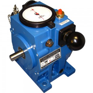
The Candy Differential, DIFF Series, is a precision timing mechanism used to advance or retard the rotary position of machine components. Installed in the drive train, these infinitely adjustable phase transmissions may be manually or motor-adjusted, while running or stopped. With the control shaft stationary, input and output shafts rotate in a 1:1, counter-rotating relationship. When a rotation is applied to the control shaft, a differential action occurs between the input and output elements making the DIFF Series ideal for positioning applications.
This unique modular design allows for a variety of accessories and mounting configurations, providing unmatched application flexibility. Through-shaft or single-shaft right angle box attachments are available to turn corners. Shaft reversing boxes are available making same-shaft rotation possible. The DIFF Series may also be fitted with a control motor allowing for remote adjustments.
The patented DIFF Series represents the latest in engineering development and is ideal for both machine retrofits and new machine designs.
Principle of Operation
The DIFF Series consists of six major components: an input shaft, an output shaft, spiral-bevel drive gears, spiral-bevel idler gears, a worm gear designated the "carrier", and a worm designated the "control shaft."
Power transfer through the Candy Differential begins at the input shaft with a spiral-bevel drive gear affixed at its inboard end. This drive gear transfers power at right angles through the idler gears, which are pinned to the carrier, and then to the output drive gear and shaft. The input and output shafts incorporate a patented backbone support system so that overhung loads are not deflected into the gear mesh. When the carrier is held stationary, the power transfer results in a 1:1 ratio transmission with counter-rotating shafts. Applying a rotation to the control shaft causes the carrier to rotate intermittently or continuously in one direction or the other. This rotation changes the position of the bevel gear assembly about the main shaft center line, causing a differential action between input and output elements. Since this control action is independent of the drive function, phase adjustments can be made while the Candy Differential is in motion providing precise position or speed control.
Options
Control Shaft :
Standard units are shipped with a control knob for manual phase adjustments. The control shaft, a keyed shaft extension, may be ordered as an option and installed in place of the standard knob.
The control shaft may then be used to mount a control motor or flexible shaft assembly. The control shaft may be installed on the knob side, the lock side, or on both sides of the Differential.
Control Motor:
The control motor option provides the capability of remote or automatic position control. The control motor is directly mounted to the Differential in place of the control knob.
The motor may be mounted on either side of the differential, or it may be mounted above the Differential using the control motor mounting bracket. Variable correction rates are available.
Right Angle Gearbox :
Right angle gearboxes are available in a 1:1 gear ratio for the DIFF 1, 7 and 20 HP units. The shafts may rotate in either direction.
The gearboxes may be mounted directly to either side of the Differential in a variety of positions and configurations including single or through-shaft options.
Shaft Reversing Gearbox :
The SR (Shaft Reversing) gearbox may be mounted to either side of the Differential in a variety of positions and may be used as the input or output element. The SR box is available for all sizes in either a 1:1 or 2:1 ratio.
The primary purpose of the SR box is to provide a same-direction rotation of the input and output shafts. The 2:1 ratio SR box may be used as either a speed reducer or speed increaser.
Technical Data
Construction:
The Candy Differential is engineered from quality materials. The housing is cast from a light weight aluminum for heat dissipation and is coated with a corrosion-resistant, USDA approved epoxy finish. The input and output shafts are stainless steel and are supported by Timken bearings for high radial load capacity. Internally, the spiral-bevel gears are picked as a set and through-hardened for precise, prolonged performance.
Input/Output Configuration:
Either drive shaft on the Candy Differential may be used as the input. The output shaft, however, will always rotate in a direction opposite that of the input. Shaft reversing boxes and right angle boxes may be added to change the direction of rotation.
Control Shaft ratio:
The relationship between the control shaft and the output is 36:1. When the control shaft is held stationary, the input and output shafts counter-rotate at a 1:1 ratio. When one full revolution is applied to the control shaft, while the differential is moving or stopped, the output shaft will advance or retard its rotary position relative to the input by 10 degrees.
The Candy Differential is infinitely adjustable in either direction. The direction of correction is dependent on the direction in which the control shaft is operated.
Position Indicator Dial:
The Candy Differential has a standard, built-in dial which indicates, in degrees, the amount of correction applied to the output shaft. The 360 degree scale provides an accurate, numerical reference of rotary position.
The Lexan protected dial may be used to reset the differential to a previously established setting. By noting a numerical position, an operator can quickly and accurately return to that position during machine setups and changeovers.
Key Lock:
The Candy Differential has a built-in lock which not only prevents unauthorized adjustments, but also ensures that the differential will not drift out of adjustment under severe vibration and load.
It is not necessary to remove the key to adjust and lock the differential. The key is chained to the unit to prevent loss; when security is a problem, the key may be removed. Three keys are provided with each unit.
Sealed-for-Life Lubrication:
The DIFF Series is factory filled to the control shaft level with Mobil SHC 634 synthetic gear oil. These units employ a sealed design to prevent contamination during operation. Under normal operating conditions, the DIFF Series is lubricated for the life of the unit.
Ceiling or wall mount configurations will require simple factory modification for oil level sight gauge and pressure relief valve relocation.
Position/Registration Control:
The Candy Differential is designed to adjust the rotary position of machine components. If a cut-off knife, for instance, is cutting short due to web stretch, repeat variation etc., the location of the tooling may be adjusted on the fly with a turn of the control knob.
When there is a variable or cumulative error, a motor-controlled differential may be used to automatically compensate for the error. Candy Controls can provide or recommend the appropriate control system necessary to monitor and maintain position control.
Mounting/Installation
The Differential housing has feet for traditional gearbox mounting. Wall mounts and ceiling mounts are also available. These alternative mounting arrangements must be specified upon ordering.
When the Candy Differential is installed in a ceiling mount arrangement, the dial indicator housing will fill with oil. In either the ceiling or wall mount arrangement, it is necessary to relocate vent and drain plug locations.
Ordering/Dimensions
Differential Specifications
Technical Information
DIFF 1
DIFF 2
DIFF 7
DIFF 10
DIFF 20
DIFF 30
HP Rating @ 1750 RPM
1
2
7
10
20
30
Shaft Diameter, inches
0.500
0.625
0.750
1.125
1.250
1.875
Maximum RPM*
1750
1750
1750
1750
1750
1750
Torque, lb-in, @ 1750 RPM
36
75
252
360
720
1080
Torque, lb-in, @ 375 RPM
57
114
400
572
1143
1715
Torque, lb-in, @ 100 RPM
85
170
595
850
1700
2550
Maximum Static Torque
135
270
900
1350
2700
4000
Maximum Over hung Load. lbs**
75
125
150
450
500
1000
Control Shaft Correction Rate
10°/turn
10°/turn
10°/turn
10°/turn
10°/turn
10°/turn
Control Shaft Torque, lb-in***
10
20
40
58
116
174
WK, Pound Inch Squared
0.7
0.82
4.75
5.36
57
59.5
Full Load Efficiency
90%
92%
94%
94%
96%
96%
Weight, Pounds
11
14
28
35
107
112
Differential Dimensions
Size
A
B
C
F
G
H
I
J
K
L
M
N
O
P
R
W
X
Z
DIFF 1
0.500
1.875
2.75
10-24
0.37
6.00
7.95
4.42
1.00
6.31
2.50
0.125
5.25
0.50
1.75
4.47
0.19
2.25
DIFF 2
0.625
1.875
*
*
*
9.00
7.95
4.42
1.50
6.31
2.50
0.187
5.25
0.50
3.25
4.47
0.19
3.75
DIFF 7
0.750
4.500
6.12
.31-18
0.75
8.75
10.12
5.81
1.50
8.75
4.25
0.187
7.75
0.63
2.12
6.97
0.38
3.29
DIFF 10
1.125
4.500
*
*
*
13.25
10.12
5.81
2.50
8.75
4.25
0.250
7.75
0.63
4.38
6.97
0.38
5.54
DIFF 20
1.250
6.500
9.00
.38-16
0.75
16.75
14.00
7.75
2.75
12.25
5.38
0.250
11.87
0.87
4.62
9.75
0.50
6.50
DIFF 30
1.875
6.500
9.00
.38-16
0.75
19.50
14.00
7.75
4.12
12.25
5.38
0.500
11.87
0.87
6.00
9.75
0.50
7.88
All dimensions are inches.
* Cannot be facemounted.
 The DIFF Series consists of six major components: an input shaft, an output shaft, spiral-bevel drive gears, spiral-bevel idler gears, a worm gear designated the "carrier", and a worm designated the "control shaft."
Power transfer through the Candy Differential begins at the input shaft with a spiral-bevel drive gear affixed at its inboard end. This drive gear transfers power at right angles through the idler gears, which are pinned to the carrier, and then to the output drive gear and shaft. The input and output shafts incorporate a patented backbone support system so that overhung loads are not deflected into the gear mesh. When the carrier is held stationary, the power transfer results in a 1:1 ratio transmission with counter-rotating shafts. Applying a rotation to the control shaft causes the carrier to rotate intermittently or continuously in one direction or the other. This rotation changes the position of the bevel gear assembly about the main shaft center line, causing a differential action between input and output elements. Since this control action is independent of the drive function, phase adjustments can be made while the Candy Differential is in motion providing precise position or speed control.
The DIFF Series consists of six major components: an input shaft, an output shaft, spiral-bevel drive gears, spiral-bevel idler gears, a worm gear designated the "carrier", and a worm designated the "control shaft."
Power transfer through the Candy Differential begins at the input shaft with a spiral-bevel drive gear affixed at its inboard end. This drive gear transfers power at right angles through the idler gears, which are pinned to the carrier, and then to the output drive gear and shaft. The input and output shafts incorporate a patented backbone support system so that overhung loads are not deflected into the gear mesh. When the carrier is held stationary, the power transfer results in a 1:1 ratio transmission with counter-rotating shafts. Applying a rotation to the control shaft causes the carrier to rotate intermittently or continuously in one direction or the other. This rotation changes the position of the bevel gear assembly about the main shaft center line, causing a differential action between input and output elements. Since this control action is independent of the drive function, phase adjustments can be made while the Candy Differential is in motion providing precise position or speed control.