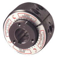
Candy Phasing Hub
Quick Facts
- Static phase adjusting coupling
- Bi-Directional angular displacement
- Infinitely variable position correction
Product Overview
The Phasing Hub is a static phase adjusting coupling designed for precise rotary positioning. When in motion, the Phasing Hub operates as a rigid 1:1 shaft coupling. Phase change of the coupling and connected shafts is accomplished with the drive stopped. By manually turning the Adjusting Ring, the Phasing Hub becomes a phase changing device providing infinitely variable and stepless phase correction in either direction.
Many machines and machine elements require precise angular adjustment between operating components. The need for this adjustment results from rotational misalignment at set-up, material deviation, wear and various other scenarios. The Phasing Hub is a unique, cost effective solution for such timing challenges.
Principle of Operation
 The Phasing Hub's operation is based on the Harmonic Drive principle. There are four primary components in each Phasing Hub: The Adjusting Ring, the Flexspline with teeth machined into its inside diameter, a Hub with the same number of teeth as the Flexspline cut into its outer diameter, and a Hub with two less teeth than the Flexspline cut into its outer diameter.
The bore of the Adjusting Ring is not round, but is ellipse-like in shape. The Flexspline, with internal teeth, is inserted into the bore of the Adjusting Ring. In this manner, the Flexspline is deflected slightly to conform to the ellipse-like shape of the Adjusting Ring. The two Hubs with external teeth then mate with the internal teeth of the Flexspline.
Under normal running conditions, there is no relative rotation of the elements, and the Phasing Hub functions as a rigid shaft coupling. However, when the Adjusting Ring is manually rotated, the assembly creates a 100:1 ratio allowing for static phase adjustments as the two Hubs with different numbers of teeth are walked around a common axis by the Flexspline. One complete rotation of the Adjusting Ring creates 3.6 degrees of phase change at the output. For micro adjustments, Candy provides a graduated scale on the Adjusting Ring, which lines up with a mark on the inner Hub. Each graduation of this scale represents 0.1 degrees of phase change on the output element.
The Phasing Hub's operation is based on the Harmonic Drive principle. There are four primary components in each Phasing Hub: The Adjusting Ring, the Flexspline with teeth machined into its inside diameter, a Hub with the same number of teeth as the Flexspline cut into its outer diameter, and a Hub with two less teeth than the Flexspline cut into its outer diameter.
The bore of the Adjusting Ring is not round, but is ellipse-like in shape. The Flexspline, with internal teeth, is inserted into the bore of the Adjusting Ring. In this manner, the Flexspline is deflected slightly to conform to the ellipse-like shape of the Adjusting Ring. The two Hubs with external teeth then mate with the internal teeth of the Flexspline.
Under normal running conditions, there is no relative rotation of the elements, and the Phasing Hub functions as a rigid shaft coupling. However, when the Adjusting Ring is manually rotated, the assembly creates a 100:1 ratio allowing for static phase adjustments as the two Hubs with different numbers of teeth are walked around a common axis by the Flexspline. One complete rotation of the Adjusting Ring creates 3.6 degrees of phase change at the output. For micro adjustments, Candy provides a graduated scale on the Adjusting Ring, which lines up with a mark on the inner Hub. Each graduation of this scale represents 0.1 degrees of phase change on the output element.Technical Data
Construction:
The Hubs are manufactured from low carbon steel and have a phosphate coating. The Adjusting Ring is also carbon steel with a black oxide coating. Applications involving hostile environments, including wash down conditions, may not be suitable for the standard materials. Please consult the factory for recommendations, including the possibility of incorporating a protective boot seal.Locking Screw:
The Phasing Hub is essentially self-locking in continuously rotating applications involving relatively low speeds and torques. In such applications, it may not be necessary to seat the locking screw located on the Adjusting Ring. However, intermittent applications involving high speeds and torques will require the use of the locking screw to maintain a desired phase setting. Once the locking screw is tightened, there is no backlash in the Phasing Hub's tooth mesh.Direction of Phase Adjustment:
As discussed in the previous sections, the Phasing Hub consists of two Hubs with different numbers of teeth. One Hub is stamped and referred to as the "S" Hub, while the other is stamped and referred to as the "D" Hub. The graduated scale (available for the PH 1000, 2500 and 5000) is mounted to the Adjusting Ring around the "S" Hub. When the "S" Hub is driven, rotation of the Adjusting Ring will cause the output to change its rotational position in the same direction as the rotation applied to the Adjusting Ring. If the Adjusting Ring is rotated in the clockwise direction, the output element will correct in the clockwise direction. If the "D" Hub is driven, the output shaft will correct in a direction opposite to the rotation applied to the Adjusting Ring. If the Adjusting Ring is rotated in the clockwise direction, the output element will correct in the counterclockwise direction.Lubrication:
The Phasing Hub is factory lubricated and will not require further maintenance under normal operating conditions. If the Phasing Hub is in a hostile environment, Candy recommends a periodic lubrication schedule. To lubricate the Phasing Hub, loosen the locking screw and remove the retaining rings from each side of the Adjusting Ring. Remove both Hubs from the Phasing Hub and generously grease the teeth with a multi-purpose lubrication. Reassemble in the reverse order, making sure that both Hubs and bores are concentric with one another. Caution, it is possible to assemble one of the Hubs off center by one tooth. Note: The Phasing Hub is not to be used as a torque multiplier nor is it designed to accommodate shaft misalignment.Mounting/Installation


 The Phasing Hub may be installed in a machine either as an in-line shaft coupling or as a concentric shaft coupling providing phase adjustment for parallel shafts.
In-Line Shaft Coupling: In order to ensure proper shaft alignment, either the driven or driving shaft should pass completely through one Hub and pilot into the other by an amount determined by the "L" dimension shown above, left.
The Phasing Hub is designed to transmit pure torque only. Radial loads and misalignment must be isolated from the Phasing Hub. This may be achieved by using shaft bearing supports or a flexible coupling adapter.
Concentric Shaft Coupling: The shaft should pass completely through the attached sprocket or gear and the Phasing Hub at a uniform diameter with a tight running fit. Refer to the illustration shown above, right.
The Phasing Hub may be installed in a machine either as an in-line shaft coupling or as a concentric shaft coupling providing phase adjustment for parallel shafts.
In-Line Shaft Coupling: In order to ensure proper shaft alignment, either the driven or driving shaft should pass completely through one Hub and pilot into the other by an amount determined by the "L" dimension shown above, left.
The Phasing Hub is designed to transmit pure torque only. Radial loads and misalignment must be isolated from the Phasing Hub. This may be achieved by using shaft bearing supports or a flexible coupling adapter.
Concentric Shaft Coupling: The shaft should pass completely through the attached sprocket or gear and the Phasing Hub at a uniform diameter with a tight running fit. Refer to the illustration shown above, right.Specifications
| Model | Continuous Torque | Bore Range | Shipping Weight |
| PH 500 | 500 lb.-in. | .250" - .500" | 1.2 lb. |
| PH 1000 | 1,000 lb.-in. | .500" - .750" | 1.5 lb. |
| PH 2500 | 2,500 lb.-in. | .750" - 1.000" | 3 lb. |
| PH 5000 | 5,000 lb.-in. | 1.000" - 1.250" | 5 lb. |
| PH 10000 | 10,000 lb.-in. | 1.250" - 1.750" | 11 lb. |
| PH 20000 | 20,000 lb.-in. | 1.750" - 2.500" | 24 lb. |
Ordering/Dimensions


| Model | A | B | C | D | E | F | G | H | J | K | L |
| PH 500 | 1.43 | .91 | .26 | .713 | .995 | 2.00 | .062/.125 | (3) 6-32-UNC-2B, on .750 B.C. | 8-32-UNF-2B | - | M3 |
|---|---|---|---|---|---|---|---|---|---|---|---|
| PH 1000 | 1.69 | 1.06 | .31 | 8.40 | 1.38 | 2.38 | .1875 | (3) 8-32-UNC-2B, on 1.125 B.C. | 10-32-UNF-2B | - | M4 |
| PH 2500 | 2.19 | 1.38 | .40 | 1.086 | 1.75 | 3.00 | .250 | (6)10-32-UNC-2B, on 1.500 B.C. | 1/4-20-UNC-2B | (4) .34 | M4 |
| PH 5000 | 2.37 | 1.63 | .37 | 1.179 | 2.17 | 3.75 | .250 | (6) 1/4-20-UNC-2B, on 1.750 B.C. | 1/4-20-UNC-2B | (4) .34 | M5 |
| PH 10000 | 3.29 | 2.06 | .61 | 1.625 | 2.94 | 4.75 | .375 | (6) 5/16-18-UNC-2B, on 2.500 B.C. | 3/8-16-UNC-2B | (4) .39 | M6 |
| PH 20000 | 4.05 | 2.38 | .84 | 2.00 | 3.75 | 6.50 | 6.25 | (6) 3/8-16-UNC-2B, on 3.125 B.C. | 1/2-13-UNC-2B | (4) .53 | M8 |
All units are inches.