Candy Switch
Electro-Mechanical and Solid-State Models Available
Quick Facts
- Dwell length and the timing of the dwell are fully adjustable from 0-360 degrees.
- Eliminate costly down time associated with trial and error machine start-ups and changeovers.
Product Overview
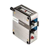
The Candy Switch is used by thousands of equipment manufacturers and users world-wide to control circuits during a machine cycle. This Candy Switch can vary the “on-off” time cycle as well as the length of “on” dwell time. Each electrically controlled machine component can be synchronized to the demands of the parent machine without custom designed cams or expensive electronic devices.
The Candy Switch is available in both solid-state and electro-mechanical models. A variety of cams and switching mechanisms allow the Candy Switch to accomodate most every industrial application. The solid-state models provide precise, repeatable timing control for over 100 million cycles.
Description
The Candy Switch series is a full line of adjustable-while-running cam switches. These electro-mechanical and solid-state switches are used to adjust the “on” and “off” points (or dwell time) of electrical or electronic circuits at any point during a machine cycle. These variable dwell devices are commonly used to control glue guns, solenoids, air and hydraulic cylinders, motors, relays, clutch-brakes and many other industrial devices.
Dwell control is just one function of this cam-switch mechanism. It is equally important to establish the “trip-on point” or timing within the machine cycle. The Candy Switch series allows a machine operator to advance or retard this timing to ensure that the dwell activates at the right point. Like the dwell control, the timing of the Candy Switch may be adjusted while the machine is running.
Since it is possible to alter both dwell and timing, the Candy switch becomes a unique tool for the machine designer and operator. The designer no longer has to calculate the rise and dwell for cams which are expensive to fabricate and modify. The machine operator no longer has to settle for “good enough” timing. With adjustable-while-running control, optimal machine performance becomes a reality.
Principle of Operation
 The Candy Switch series is comprised of five major components: an input shaft, a rotating cam, a switching mechanism, a dwell control assembly and a timing control assembly. The only components which change depending on the model of Candy Switch (electro-mechanical or solid-state) are the cam and the switching mechanism.
To actuate the switch, the input shaft must be coupled, in some manner, to a rotating member of the parent machine. The Candy Switch is a 1:1 unit, meaning that one full revolution of the input shaft represents one full cycle of the dwell and timing set points. If one revolution of the input shaft does not match the machine cycle, a ratio must be added between the parent machine and the Candy Switch, bringing these relationships back to a 1:1 ratio.
Rotating the input shaft causes the cam to rotate via a parallel-shaft and helical gear arrangement. In electro-mechanical Candy Switches, the cam has a physical, uniformly increasing rise which rotates over a snap action type switch or air valve. When the nylon roller of the switch hits the rise, the circuit "trips on" until the cam rotates and the nylon roller falls off the rise, thus turning the circuit "off".
Solid-state Candy Switches employ a solid cam wrapped with a two-tone reflective material. The solid-state cam rotates above a photo sensor which is part of the solid-state switching mechanism.
The switching mechanism activates both the dwell and the timing by opening or closing a circuit based on the cam location. This mechanism also serves as the terminal block for incoming and outgoing signals or voltages. Electro-mechanical switches typically incorporate a snap action type micro switch or a two or three way air valve. Solid-state switching mechanisms are typically photo sensor based boards which pick up a reflective pattern off a printed cam.
The unique internal design of the Candy Switch permits on-the-fly control of both circuit dwell and timing. The dwell control assembly increases or decreases the dwell by moving the cam back and forth over the switching mechanism. Circuit timing is achieved by rotating the cam on its axis over the switching mechanism. Both adjustments are actuated by the respective control knobs on the front face of the Candy Switch.
Most models provide a full 360° range for both timing and dwell. The values for these setpoints may be monitored from the reference scale on top of the Candy Switch.
The Candy Switch series is comprised of five major components: an input shaft, a rotating cam, a switching mechanism, a dwell control assembly and a timing control assembly. The only components which change depending on the model of Candy Switch (electro-mechanical or solid-state) are the cam and the switching mechanism.
To actuate the switch, the input shaft must be coupled, in some manner, to a rotating member of the parent machine. The Candy Switch is a 1:1 unit, meaning that one full revolution of the input shaft represents one full cycle of the dwell and timing set points. If one revolution of the input shaft does not match the machine cycle, a ratio must be added between the parent machine and the Candy Switch, bringing these relationships back to a 1:1 ratio.
Rotating the input shaft causes the cam to rotate via a parallel-shaft and helical gear arrangement. In electro-mechanical Candy Switches, the cam has a physical, uniformly increasing rise which rotates over a snap action type switch or air valve. When the nylon roller of the switch hits the rise, the circuit "trips on" until the cam rotates and the nylon roller falls off the rise, thus turning the circuit "off".
Solid-state Candy Switches employ a solid cam wrapped with a two-tone reflective material. The solid-state cam rotates above a photo sensor which is part of the solid-state switching mechanism.
The switching mechanism activates both the dwell and the timing by opening or closing a circuit based on the cam location. This mechanism also serves as the terminal block for incoming and outgoing signals or voltages. Electro-mechanical switches typically incorporate a snap action type micro switch or a two or three way air valve. Solid-state switching mechanisms are typically photo sensor based boards which pick up a reflective pattern off a printed cam.
The unique internal design of the Candy Switch permits on-the-fly control of both circuit dwell and timing. The dwell control assembly increases or decreases the dwell by moving the cam back and forth over the switching mechanism. Circuit timing is achieved by rotating the cam on its axis over the switching mechanism. Both adjustments are actuated by the respective control knobs on the front face of the Candy Switch.
Most models provide a full 360° range for both timing and dwell. The values for these setpoints may be monitored from the reference scale on top of the Candy Switch.
Dwell
 To provide an infinitely adjustable dwell or "on-time" period, a cam of uniformly increasing rise is employed to activate the switch. Shifting the cam on its hex drive shaft alters the percentage of rise area in contact with the switch roller. This design allows dwell time to be varied from 0-360° even while running.
Timing
 To provide infinite timing adjustment of the switch "trip-on" point, a pair of helical gears are arranged so that when the shorter gear is shifted on its hex shaft, a rotary motion is imparted which causes a change in phase relationship. Full travel allows over 360° of phase timing, even while running.
Electro-Mechanical Model
There are two basic types of electro-mechanical Candy Switches which can be determined by the switching mechanism. The first type employs a snap action type switch to open and close the circuit. The second type uses a two or three-way air valve as the switching mechanism. The standard cam for all electro-mechanical models is the CS-12. The CS-12 cam provides a full 0-360° range for both dwell and timing. Model A
General Purpose Switch
A 20 amp, single pole, double throw, snap action switch.
Speed to 500 cpm.
Switch mechanical life-
100 million cycles.
Model B
Air Valve
A cam actuated poppet valve suitable
for air, vacuum, and some fluid applications.
Barbed fittings for 1/8" plastic tubing.
Specify: 2-way or 3-way valve.
Model D

Model K
Hall Effect, Solid-State Cam Operated Switch
An integrated circuit produces a digital output, with not contacts (the output is bounce free). 100 million cycle life.
Specify: Model K5 (5VDC) or Model K16 (6 to 16 VDC). Current sinking circuit.
Electro-Mechanical Cams
CS-12
Standard cam for clockwise rotation. The CS-12 provides a 0-360º range for both dwell and timing.
CS-12C
Optional cam for counter-clockwise rotation. The CS-12C provides a 0-360º range for both dwell and timing.
Solid State Model
 Model AT/DT
Conditioned, High Current Signals
The AT/DT series is a general purpose AC or DC solid-state switch. The AT prefix refers to an AC switching voltage (10 amp max. current) and uses an optically isolated triac controlled switching mechanism. This triac is a zero crossing device. The DT prefix, refers to applications involving a DC switching voltage. The DT switch uses a transistor controlled switching mechanism (4 amp max. current). The standard cam for the AT/DT series is the N cam.
Model N
Conditioned, Low Current Signals The model N uses a photo sensor consisting of a light emitting diode and a phototransistor. The N board contains an amplifier circuit allowing for direct interface with programmable controllers or other electronic devices. The Model N provides both an active high and an active low output, providing complete flexibility in meeting interface requirements. The active low output (WLA) features an open collector output allowing an external pull-up resistor to a voltage between 0 and + 25V. The standard Model N is supplied with an N cam. Please specify 12V or 5V model when ordering. Supply current (excluding output loading): 12- Volt Model - 25 mA, 5- Volt Model - 18mA.
Model F
 Unconditioned Signals
The Model F is primarily for voltage dependent circuits. The F board contains only a terminal strip, a 1k limiting resistor and the photo scanner. Additional circuitry must be provided by the user to suit specific applications. The standard cam for this model is the F cam.
Unconditioned Signals
The Model F is primarily for voltage dependent circuits. The F board contains only a terminal strip, a 1k limiting resistor and the photo scanner. Additional circuitry must be provided by the user to suit specific applications. The standard cam for this model is the F cam.
 The block diagram is a suggestion for use of this scanner. In most cases a forward current of 10 MA will provide sufficient radiation from the emitter to generate the on signal from the sensor.
A Schmitt trigger circuit is necessary to provide hysteresis between the light and dark surface of the cam. This eliminates any possible oscillations in a solid state output.
The electrical rating for this device is:
The block diagram is a suggestion for use of this scanner. In most cases a forward current of 10 MA will provide sufficient radiation from the emitter to generate the on signal from the sensor.
A Schmitt trigger circuit is necessary to provide hysteresis between the light and dark surface of the cam. This eliminates any possible oscillations in a solid state output.
The electrical rating for this device is:
| ON state | OFF state | |
|---|---|---|
| Sensor | Ic Min = 100 uA @ If = 40 mA @ Vce = 5V | Collector-Emitter Breakdown: 50V Max Leakage: 25 nA @ Vce = 30V |
| Emitter | If Continuous = 40 mA Max Vf @ 40mA = 1.6V Max | Reverse Voltage = 2V Max |
Model P
 Proximity Sensor
The model P is a self contained proximity sensor which reads a foil wrapped cam. The Model P is the only switch in the solid-state family that is restricted to one type of cam. The P cam offers a 0-360° range of adjustability for both dwell and timing. Specify NPN or PNP.
Electrical Characteristics:
Supply voltage: 12-24 VDC
Max continuous load: 200 mA
Max current consumption (excluding load): 10mA @ 12V. 20mA @ 24V.
RL min: @ 12V=68 ohms. @ 24V=130 ohms.
Proximity Sensor
The model P is a self contained proximity sensor which reads a foil wrapped cam. The Model P is the only switch in the solid-state family that is restricted to one type of cam. The P cam offers a 0-360° range of adjustability for both dwell and timing. Specify NPN or PNP.
Electrical Characteristics:
Supply voltage: 12-24 VDC
Max continuous load: 200 mA
Max current consumption (excluding load): 10mA @ 12V. 20mA @ 24V.
RL min: @ 12V=68 ohms. @ 24V=130 ohms.
N Cam
 0 to 360° Dwell & Timing Cam
Rotation: Clockwise
Dwell: Normally open
0 to 360° Dwell & Timing Cam
Rotation: Clockwise
Dwell: Normally open
NC Cam
 0 to 360° Dwell & Timing Cam
Rotation: Counterclockwise
Dwell: Normally closed
0 to 360° Dwell & Timing Cam
Rotation: Counterclockwise
Dwell: Normally closed
F Cam
 0 to 360° Dwell & Timing Cam
Rotation: Clockwise
Dwell: Normally closed
0 to 360° Dwell & Timing Cam
Rotation: Clockwise
Dwell: Normally closed
FC Cam
 0 to 360° Dwell & Timing Cam
Rotation: Counterclockwise
Dwell: Normally closed
0 to 360° Dwell & Timing Cam
Rotation: Counterclockwise
Dwell: Normally closed
H Cam
 0° to 30° Dwell Cam
Rotation: Clockwise or counter-clockwise
Dwell: 0-30°
Timing: Adjustable from 0-360°
0° to 30° Dwell Cam
Rotation: Clockwise or counter-clockwise
Dwell: 0-30°
Timing: Adjustable from 0-360°
G Cam
 Rotation: Clockwise or counter-clockwise
Pulses: 0-10 equally spaced pulses with a pulse duration of approximately 22°
Rotation: Clockwise or counter-clockwise
Pulses: 0-10 equally spaced pulses with a pulse duration of approximately 22°Technical Data
Construction:
The Candy Switch housing is a gasketed aluminum cast providing a NEMA-12 dust tight, drip proof rating. The input shaft is steel with a black oxide finish and is supported by self-lubricating bushings. The reference scale on top of each unit is available in glass or Lexan plastic. Each Candy Switch model has (2) 1/2" NPT outlets to accommodate circuit connection.Dwell and Timing:
When setting up and adjusting the Candy Switch, it should be noted that the dwell and timing are independent adjustments. A change in the timing does not affect the dwell. However, a change in the dwell may affect the timing, depending on whether the dwell adjustment is made on the leading edge or trailing edge of the cam.
Reference Scale:
Each Candy Switch model has a reference scale located on top of the switch. This scale defines relative values for both dwell and timing. Operators may use this scale to define limits of adjustment or to return to a previously established set of values. Standard models are shipped with glass scales, however, Lexan plastic scales are available when glass is not suitable.
Repeatability:
The Candy Switch series is typically accurate to within 1/2 to 1% with slight variations depending on the model and operating speeds.Banking:
Any number of Candy Switches may be banked together for multiple circuit control. Different models may be mixed in the bank depending on application requirements. Four (4) 1/4"-20 threaded rods are required as tie rods through the bank. The CS-30 banking gears (one per switch) may be used to gear the switches together. In this arrangement, Candy recommends that every other switch be ordered to run in the opposite direction as the one before it. An alternative to this banking arrangement employs the CS-56 Idler Gear Unit between switches. This serves to separate the Candy Switches by 3/8" allowing for a third gear in the train causing each input shaft to rotate in the same direction. See accessory notes for more details.Mounting/Installation
The Candy Switch may be mounted in any position and may be driven in either the clockwise or counterclockwise direction. Most designers use one of four methods to tie the Candy Switch input shaft to the parent machine's line shaft or rotating member: Direct coupling, chain drive, belt drive or gear drive. It is important to note that the machine cycle must have a 1:1 relationship with the input shaft of the Candy Switch. Various accessories may be used when installing a Candy Switch. The CS-35, mounting bracket may be used for a standard foot mount arrangement.The Candy Switch may also be mounted to the side frame of the machine using the (4) 1/4" mounting holes located in each corner of the housing. The CS-30 Banking Gears and the CS-56 Idler Gear Unit may be used when |
 |
| Direct coupling | Chain drive |
 |
 |
| Timing belt | Gear drive |
Ordering/Dimensions
When ordering a Candy Switch, it is important to: 1. Decide whether an electro-mechanical or solid-state version is best suited for the application. 2. Choose the appropriate Candy Switch model based on desired dwell time, direction of rotation, operating and switching voltages. The following specification chart may assist you in choosing the most appropriate model for your application. Please note that all of the specifications in this chart are based on the standard cam for each unit.| Model | Switch/ Board | Cam | Scale | Operating Rotation | Switched Voltage | Dwell Voltage | Time | Specify |
|---|---|---|---|---|---|---|---|---|
| A | A | CS-12 | S | CW | - | 120VAC/DC | N.O. | |
| A/C | A | CS-12C | R | CCW | - | 120VAC/DC | N.O. | |
| B | B | CS-12 | S | CW | - | Pneumatic | N.O. | 2 or 3 way Valve |
| K | K | CS-12 | S | CW | 5VDC or | 6-16 VDC | N.O. | K5 or K16 |
| N | N | N | S | CW | 12VDC | 12VDC | N.O. | |
| F | F | F | S | CW | 12VDC | 12VDC | N.C. | |
| G | N | G | 0-10 | either | 12VDC | 12VDC | N/A | |
| P | - | P | S | CW | 10-30VDC | 55mA@12V | N.O. | NPN or PNP |
| AT/12D | AT | N | S | CW | 12VDC | 5-400VAC | N.O. | |
| AT/24D | AT | N | S | CW | 24VDC | 5-400VAC | N.O. | |
| AT/90D | AT | N | S | CW | 90VDC | 5-400VAC | N.O. | |
| AT/120A | AT | N | S | CW | 120VAC | 5-400VAC | N.O. | |
| DT/12D | AT | N | S | CW | 12VDC | 90VDC | N.O. | |
| DT/24D | AT | N | S | CW | 24VDC | 90VDC | N.O. | |
| DT/90D | AT | N | S | CW | 90VDC | 90VDC | N.O. | |
| DT/120A | AT | N | S | CW | 120VAC | 90VDC | N.O. |
| Dimensions |
|---|
 |
| Accessories | |
|---|---|
CS-35 |
CS-30 |
 |
 |
CS-34 |
CS-56Idler Gear Unit |
 |
 |