
CL24 SERIES DESCRIPTION
Disc Coupling
Candy’s CL24 Series double clamp disc coupling is a heavy duty version of the classic aluminum disc coupling. The CL24’s body is steel, and its shafts are secured on each side via a double clamping connection. With a thicker plate spring made with more layers, this coupling is an ideal option for applications requiring high rigidity and torque.
• Double clamp design provides stronger shaft connection
• High torque, high rigidity applications
• Zero backlash, flexible shaft design
• Inch, metric an mixed bores available
Options
#45 Steel Body
Stainless Steel Plate Springs
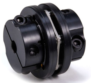
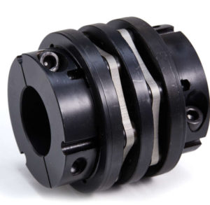
Single Disc
Double Disc
Double Clamping Shaft Connection
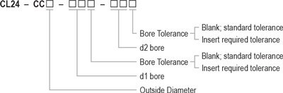
Ordering Information

Back to Top
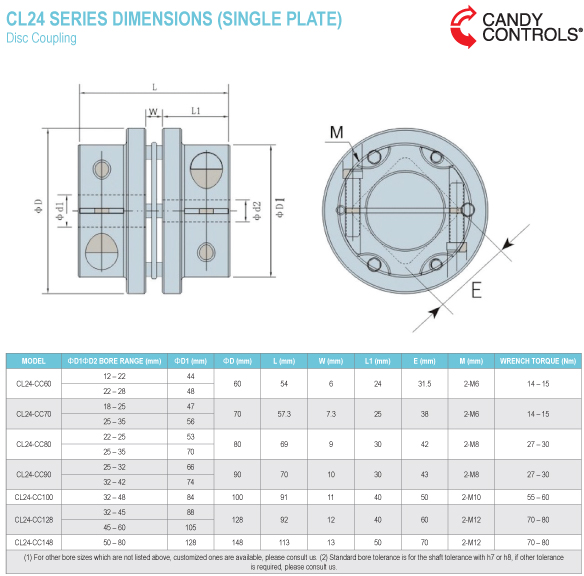
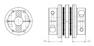
CL24 SERIES DIMENSIONS (DOUBLE PLATE)
Disc Coupling
Use precautions:
- Be sure to observe allowable tolerances of eccentricity, angular misalignment and endplay between shafts.
- Bolts must be tightened with specified torque.
- The concentricity of the left and right inner diameters of the coupling can be assembled accurately by using special fixtures. In case of strong impact on the coupling, the assembly accuracy may be adversely affected and continued use may damage the coupling.
- The temperature range is – 30°C to 120°C. Despite water and oil resistance, extreme adhesion can also lead to deterioration of the product, avoid this kind of situation.
- Plate springs consist of thin stainless steel diaphragms, when using, care should be taken to avoid damage to the plate springs.
- Do not tighten the clamping bolt before inserting the installation shafts.
Installation:
- Confirm whether the clamping bolts are loose. Remove rust, dust and oil on the inner diameter of the coupling and the shafts. Lubricants and contaminants can have a significant impact on the friction coefficient of the coupling and must be removed.
- Insert the coupling onto the motor or driving shaft. When mounting, do not apply excessive compression or tension force on the components of the coupling, especially when inserting the coupling onto the driven shaft. Excessive compression force may damage the coupling.
- Shafts should be fully inserted along the length of each flange/hub (L shown below),but must not interfere with the elastic element and plate springs. Tighten the clamping screws alternately until the coupling is temporarily fixed in place between the two shafts, but can be rotated slightly by hand.
- Place a micrometer on the clamping hairpin outer diameter (as shown below) of the motor or driving shaft side, adjust and tighten the clamping bolts while rotating the motor or driving shaft side by hand, so that the difference between the high point values of figure A and B shown below is 0.02 mm or less (as close as possible to zero). If this value cannot be achieved, remove coupling and realign both shafts then repeat.
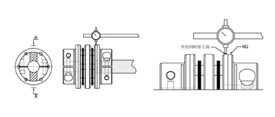
- Once high point tolerances are achieved, tighten both sets of clamping bolts, alternately, to the correct tightening torque shown in the parameter table using a calibrated torque wrench. Check driven hub again with micrometer to confirm high point values are still within the allowable tolerance.
- As an anti-loosening measure, it is recommended that clamping bolts be re-tightened to specified torque after a certain period of operation.