
CL26 SERIES DESCRIPTION
Disc Coupling
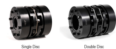
Candy’s CL26 Series locking assembly type couplings transmit rotational power between two shafts through a friction connection. Each shaft end is locked to the disc coupling through a shrink disc mechanism integral to each hub providing even pressure distribution on the shafts. The CL26 accommodates angular misalignment and shaft end play via the stainless steel spring plate assembled between the steel hubs. This compact design is ideal for servo motor applications thanks to its high torque, high rigidity and high response characteristics.
• Even connection pressure distribution around both shafts
• High rigidity, high torque, high response
• Zero-backlash, flexible shaft
• Inch, metric and mixed bores available
Options
Steel Body
Stainless Steel Plate Springs
Single Disc
Double Disc
Locking Assembly Shaft Connection
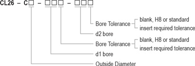
Ordering Information
Back to Top
CL26 SERIES INSTALLATION
Disc Coupling
Use precautions:
- Be sure to observe allowable tolerances of eccentricity, angular misalignment and endplay between shafts.
- Bolts must be tightened to specified torque.
- The concentricity of the left and right inner diameters of the coupling can be assembled accurately using special fixtures. In case of strong impact on the coupling, the assembly accuracy may be adversely affected and continued use may damage the coupling.
- The temperature range is – 30 C to 120 C. Despite water and oil resistance, extreme adhesion can lead to deterioration of the product, avoid these conditions.
- Plate springs consist of thin stainless steel diaphragms, be careful not to damage plate springs.
- Do not tighten the clamping bolts before inserting shafts.
Installation:
- Confirm the tightening bolts are loose. Remove rust, dust and oil on the shaft and the inner diameter of the coupling. Lubricants and contaminants can have a significant impact on the friction coefficient of the coupling and must be removed.
- Insert the coupling onto the motor/driving shaft and driven shaft. When installing, do not apply too much compression or tensile force on the elastic element/plate springs, especially when mounting the coupling onto the driven shaft.
- When the compression/tightening bolts are loose, confirm the coupling can move slightly along the axial and rotation directions. If movement is not smooth, readjust the centering of the two shafts. This method is recommended as a simple confirmation method of left and right concentricity. If this confirmation method cannot be used, use other measurement methods to confirm installation accuracy.
- After shaft and coupling alignment are adjusted, tighten the compression bolt slightly, diagonally or alternately.
- After confirming that there is no compression or tension in the axial direction, tighten the compression bolts in diagonal sequence. When tightening the bolts, use a calibrated torque wrench and tighten to the tightening torque in the parameter table.