
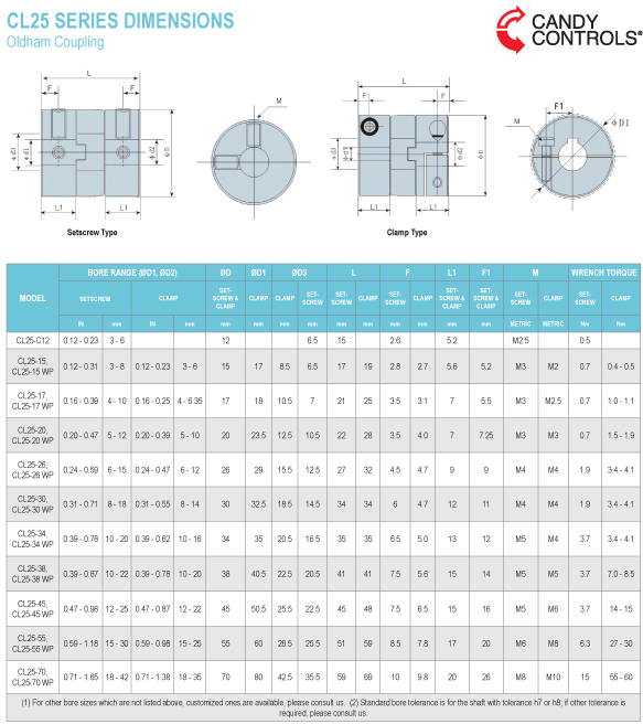
CL25 SERIES DESCRIPTION
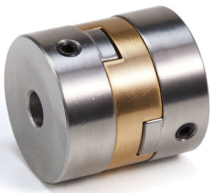
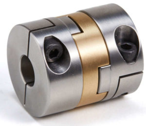
Candy’s CL25 Series Oldham couplings feature stainless steel hubs and a copper insert. The higher durability copper insert increases the operating temperature range and greatly reduces wear, allowing the CL25 to maintain its zero-backlash rating longer than traditional Oldham couplings. The CL25 is designed for high torque, high response applications with a high amount of parallel misalignment.
• High torque, high torsional stiffness, high response
• Absorbs parallel and angular misalignment
• Zero-backlash, flexible shaft
• Inch, metric and mixed bores available
Options
Stainless Steel Hubs
Copper Insert
Setscrew
Keyway and Setscrew
Clamp Collar
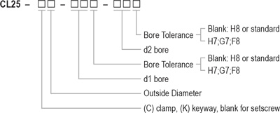
Ordering Information
Back to Top
Use precautions:
- Be sure to observe allowable tolerances of eccentricity, angular misalignment and endplay between shafts.
- Bolts must be tightened to specified torque.
- Temperature range is – 20°C to 120°C. Despite water and oil resistance, extreme adhesion can lead to deterioration of the product, avoid these conditions.
- Do not tighten the clamping bolts before inserting the installation shafts.
Installation:
- Confirm whether the clamping bolt and positioning screw are loose. Remove the rust, dust and oil on the shaft and the inner diameter of the coupling. Lubricants and contaminants can have a significant impact on the friction coefficient of the coupling and must be removed.
- Insert the coupling onto the motor or driving shaft. When installing, do not apply too much compression or tensile force on the coupling, especially when inserting the coupling onto the driven shaft. Too much compression force may damage the coupling.
- When the clamping bolts or positioning screws are loose, please confirm the coupling can move slightly along the axial and rotation directions. If movement is not smooth, please readjust the centering of the two shafts. This method is recommended as a simple confirmation method of left and right concentricity. If the same confirmation method cannot be used, please use other measurement methods to confirm installation accuracy.
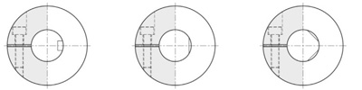
- In principle, the installation shaft is a circular shaft. When using a non-circular shaft, please pay attention to the installation
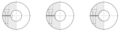
position shown in the figure below (pay attention not to make the keyway, d-groove enter the side of the coupling shaded in gray). Improper installation position of the shaft may cause damage to the coupling and decrease the shaft clamping force. To obtain satisfactory coupling performance, we recommend the use of round shafts.Recommended installation method:
Installation method not recommended:
- After confirming that there is no compression, tension and other forces in the axial direction, tighten the clamping bolts or positioning screws. When tightening the bolts, use a calibrated torque wrench and tighten according to the tightening torque range listed in the parameter table.
- As an anti-loosening measure, it is recommended to use correct tightening torque again for re tightening clamping screws after a period of operation.