CL12 SERIES DESCRIPTION
Encoder Coupling
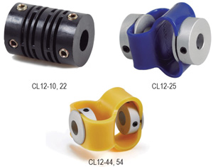
CL12 Series Encoder Couplings connect encoders, resolvers and other feedback devices to production machines. The CL12 absorbs misalignment and provides electrical isolation which helps protect machine electronics from “noise.”
• High strength polyester resin with glass fibers
• Engineered for a variety of encoder applications
• Zero-backlash, flexible shaft
• Low inertia, high speed
• Provide electrical isolation

Options
Fiberglass Beam
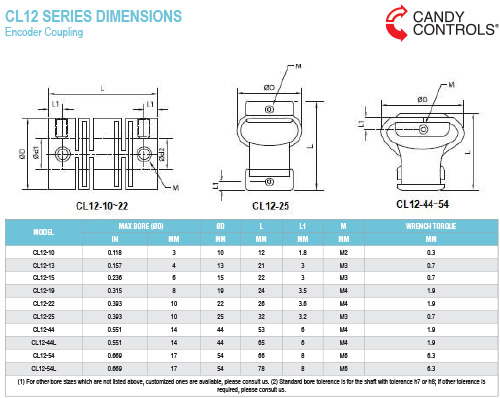
-CL12-10, 13, 19, and 22
Aluminum Hubs with Elastomer Insert
-CL12-25, 44, and 54
Setscrew
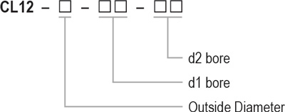
Ordering Information

Back to Top
CL12 SERIES INSTALLATION
Encoder Coupling
Use precautions:
- Be sure to observe allowable tolerances of eccentricity, deflection and axis.
- Bolts must be tightened to specified torque.
Installation:
- Confirm whether set screws are loose, and remove rust, dust and oil on the inner diameter of the coupling and shaft. Lubricants and contaminants have a significant impact on the friction coefficient of the coupling must be removed.
- Please insert the coupling onto the motor or driving shaft. When installing, do not apply too much compression or tensile force on the coupling, especially when inserting the coupling onto the driven shaft.
- When the set screws are loose, please confirm that the coupling can move slightly along the axial and rotation directions. If the movement is not smooth, please readjust the centering of the two shafts. This method is recommended as a simple confirmation
method of left and right concentricity. If the same confirmation method cannot be used, please use other measurement methods to confirm installation accuracy.
 Candy Controls
When Timing is Everything


