
CL5 SERIES DESCRIPTION
Disc Coupling
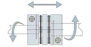
Candy’s CL5 Series is a zero-backlash, flexible shaft servo disc coupling that features low inertia, high torque and excellent response. Its stainless steel plate springs absorb misalignment, helping avoid premature failure, while identical clockwise and counterclockwise rotational characteristics provide versatility for a wide variety of automation applications.
• Robust, torsionally stiff servo coupling
• Durable clamp type couplings
• Zero-backlash, excellent response
• Inch, metric and mixed bores available
Options
Aluminum 6061
Stainless Steel Plate Springs
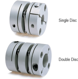
Single Disc
Double Disc
Clamp
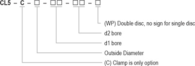
Ordering Information
Back to Top
CL5 SERIES INSTALLATION
Disc Coupling
Use precautions:
- Be sure to observe allowable tolerances of eccentricity, deflection and axis.
- Bolts must be tightened with specified torque.
- The concentricity of the left and right inner diameters of the coupling can be assembled accurately by using special fixtures. In case of strong impact on the coupling, the assembly accuracy may not be maintained and the coupling may be damaged in use, please pay attention to it during operation.
- The temperature range is – 30 C to 120 C. Despite water and oil resistance, extreme adhesion can also lead to deterioration of the product, avoid this kind of situation.
- Plate springs consist of thin stainless steel diaphragms, when using, care should be taken to avoid damage to the plate springs.
- Do not tighten the clamping screws before inserting the installation shaft.
Installation:
- Confirm whether the clamping screws are loose or not, remove rust, dust and oil on the inner diameter of the coupling and shaft. In particular, grease and other lubricants which have a significant impact on the friction coefficient of the coupling must be removed.
- Please insert the coupling onto the motor shaft or driving shaft. When inserting, do not apply excessive compression or tension force on the elastic components of the coupling, especially when inserting the coupling into the driven shaft after installing the coupling to the motor/driving shaft.
- Before clamping screws are tightened, make sure the coupling can move slightly along the axis and rotation direction. lf it cannot move smoothly, readjust the centering of the two axes. This method is recommended as a simple method to confirm the left and right concentricity. If the same method cannot be used, please use other measuring methods to confirm the installation accuracy.
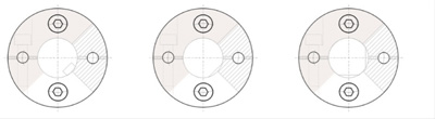
- In principle, the installation shaft is a circular shaft. When using a non-circular shaft, please pay attention to the installation position shown in the figure below. (please pay attention not to make the keyway, d-groove enter the gray part of the side). Improper installation position of the shaft may cause damage to the coupling and decrease the shaft clamping force. To obtain satisfactory coupling performance, we recommend the use of round shafts.
Recommended installation method:
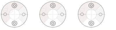
Installation method not recommended:
- The length of coupling insertion on both shafts is shown in the figure below, so that the installation shaft runs through the full length of the flange at the side section (L1 size) and does not interfere with the elastic element and the other side of the shaft. Please control the clamping flange face-to-face dimension (W dimension) within the allowable error range of axial displacement relative to the standard value. This value is the allowable value for assuming eccentricity and zero offset angle. Please adjust it as small as possible.
- After confirming that there is no compression, tension and other forces in the axial direction, please tighten the clamping screws with a verified torque wrench based on the tightening torque range listed in the parameter table.
- As an initial anti-loosening measure, it is suggested to re-tighten the clamping screws after running for a period of time.