CL6 SERIES DESCRIPTION
Bellows Coupling
Candy’s CL6 is a zero-backlash, flexible shaft Bellows coupling designed with performance
characteristics required by a number of motion control applications. Its spring action Bellows
configuration absorbs parallel and angular misalignments and shaft end play, while being torsionally
stiff enough to provide excellent response.
• Low inertia, high response motion control couplings
• Identical clockwise and counterclockwise rotational characteristics
• High torque capacity and excellent response
• Spring action Bellows absorbs misalignment
Options
Aluminum 6061 Hubs
Stainless Steel Bellows
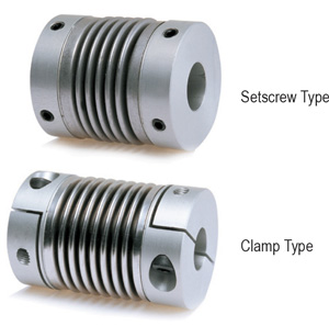
Setscrew
Keyway and Setscrew
Clamp
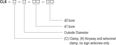
Ordering Information
Back to Top
CL6 SERIES INSTALLATION
Bellows Coupling
Use precautions:
- Be sure to observe allowable tolerances of eccentricity, deflection and axis.
- Bolts must be tightened to specified torque.
- The temperature range is – 20°C – 80°C. Despite water and oil resistance, extreme adhesion can also lead to deterioration of the product, avoid this kind of situation.
- Do not tighten the set screws or clamping screws before inserting the shafts.
Installation:
- Confirm whether the set screws or clamping screws are loose, and remove rust, dust and oil on the shaft and the inner diameter of the coupling. Various lubricants and contaminants have a significant impact on the friction coefficient of the coupling and must be removed.
- Please insert the coupling onto motor or driving shaft. When inserting, do not apply too much compression and tensile force on the coupling, especially when inserting the coupling onto the driven shaft after installing the coupling to the motor/driving shaft.
- When the set screws or clamping screws are loose, please confirm whether the coupling can move slightly along the axial direction and rotation direction. If the movement is not smooth, please readjust the centering of the two shafts. This method is recommended as a simple confirmation method of left and right concentricity. If the same confirmation method cannot be used, please use other measurement methods to confirm the installation accuracy.
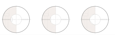
- In principle, the installation shaft is a circular shaft. When using a non-circular shaft, please pay attention to the installation position shown in the figure below. (please pay attention not to make the keyway, d-groove enter the gray part of the side). Improper installation position of the shaft may cause damage to the coupling and decrease the shaft clamping force. To obtain satisfactory coupling performance, we recommend the use of round shafts.
Recommended installation method:
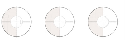
Installation method not recommended:
- After confirming that there is no compression, tension and other forces in the axial direction, tighten the set screws or clamping screws by a verified torque wrench based on the tightening torque range listed in the parameter table.
- As an anti-loosening measure, it is recommended to use correct tightening torque again for re-tightening screws after a period of operation.